|
rf9585a.exe Reference Disk v1.11 (zipped image)
rd9585a.exe Diagnostic Disk v1.11 (zipped image)
postbios.exe BIOS Flash Update v1.10/1.11* (zipped image)
Updates BIOS to revision level 02. Needed to support ECC-P.
* IBM had this marked as v1.11 on their servers, the floppy itself reports v1.10.
192-224 IBM PS/2 Server 85 (9585-0X6, 0XA and 0XF)
193-207 IBM PS/2 Server 85 (9585-0XG)
486 Interposers and Upgrades
Specifications
Memory
Features
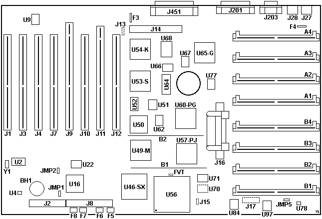
9585 X Planar
9585-X Supports Display Panel!
EE Floppy Support
What is ECC-P?
ASCII Terminal
Onboard SCSI
Maximum IML Drive Size
X Without IML Partition?
ADF Sections
Memory
RAM
- 2, 4, and 8 MB 70 ns parity SIMMs for a max of 64 MB.
- Supports SIMMs of different speeds and sizes and single SIMM installations
- (sounds like the Type 2 H/L complex)
Cache
- L1: 8 KB (486SX)
- L2: no L2 cache
Features
The PS/2 Server 85 (announced Sept 21, 1992) was to replace the PS/2 Model 80.
9585 X Planar FRU P/N 92F0270, P/N 71G6646, "THE DELIVERY BOYS"
Note: Two different layouts of the board exist.
The most notable difference is the position of the F5-F8 PTC fuses. On the
other variant the fuses are shifted to the right with F5 & F6 being
directly below U46-SX.
This planar uses the same core logic as the
Upgrade Type-A Complex and
PS/55 Model 5551-N/Y.
U70 solder pads for another oscillator.
Possibly a different CPU speed? Like 25MHz?
J15 Three pin header marked "55" and "66"
FVT is what? Small outline, not big enough
for a normal header. Not sure. Maybe something to switch between an ODP and ODPR?
Need to test where the traces go...
F5-8 PTC fuses on the planar power traces
(like 85-K/N and 95A planars).
J13 - SCSI Diagnostic Port
| Pin | Description |
|---|
| 1 | RXD (U33 pin 45) |
| 2 | Ground |
| 3 | N/C (key) |
| 4 | TXD (U33 pin 93) |
Not populated. The port can be used to access the
Serial Console.
9585-X Supports Display Panel!
Major Tom:
Just checked, and the 85-X BIOS contains pretty much the same
checkpoint routines as the later 90/95 T4 and 85-K/N SurePath BIOS. It outputs
the CP codes to ports 108 - 10Fh as the other systems do, and the checkpoint
routines are actually being called by the POST code. So if the planar logic
indeed is there, you should see the CP codes on the Op Panel [when you plug it
in place of the stock Indicator Panel].
David Beem:
Confirmed - I have a spare panel displaying information when I did
nothing more than unplugging the speaker/power switch board and plugged it
in.
9585-X Operator Panel Support Components, Front
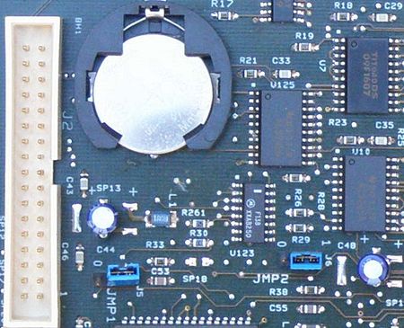
U123 (74F138),
U125 (74ALS245),
and R261 (10 kΩ, pkg #0805) are populated.
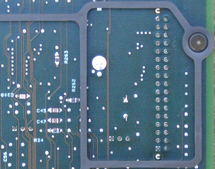
9585-X Operator Panel Support Components, Back
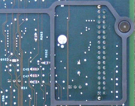
R262 (100 Ω, pkg #0805) and R263 (30 - 70 Ω, pkg #0805) are populated.
9585-X Planar close-ups from David Beem.
EE Floppy Support
From Su Wadlow:
The 9585 X models have the 44-pin connector needed for use of the
electronic eject floppy. Just waiting on software...
What is ECC-P?
ECC-P support is BIOS code that provides for selectable memory error
detection and correction of single bit errors (detection only of all double bit
errors and some 3- and 4-bit errors) using standard FPM. With ECC-P the
detection and correction takes place in the memory controller rather than in
the ECC SIMM as on the Server 95.
For more on this fascinating subject, go
HERE.
ASCII Terminal
The IBM PS/2 Model 85 contains a console select utility that allows systems
console operations to be performed by an ASCII terminal via the system
asynchronous communications port (serial port) pre-installed on the system hard
disk. If this option is selected, an ASCII terminal must be connected to the
serial port at the time of selection.
Onboard SCSI
From Peter Wendt:
The onboard SCSI of the 95xx is often referred as "Spock-Prime"
- and is (almost) identical to the later SCSI with cache... with the exception
of the cache, which it hasn't got. From the design it is *very* similar to the
short SCSI without cache, which has an 80C188-16 as well. The SCSI microcode
however is part of the machine BIOS stored in a single small 16-bit PLCC EPROM
if I remember correctly. There is a part of the SCSI code also included in the
IML. This adapter can be found on the 9556/9557, the "Bermuda" 9576/9577 - and
the "small" 9585-0Xx.
If you look closely at the 9585-xXx planar you will find some SMD transistor
"of the bigger kind" and some stuff that looks like "auto-termination". In
addition the onboard SCSI adapter of the "Spock-Prime" is described as "SCSI-2
compliant"... which extends on the command set in the first place, the
enhanced SCSI translation and on the electric interface as well I think. But
not on the speed of course, which is 5 MB/s SCSI-1 standard.
David Beem elucidates:
As David Beem's SCSI microcode
levels shows, the 9585 'X' SCSI microcode is specifically held in U51 (not
contradicting Peter at all, but actually confirming his memory is correct &
enhancing the statement). The 25h/37d microcode level is pretty standard for a
few different IBM SCSI adapters & planars (and the same FRU-numbered EPROM
is also used on the Bermuda planar). Conceivably it could be upgraded to a
26h/38d level with a burner & soldering skills (at what benefit is
unknown).
Although the newer BIOS image (for lack of a better term) wouldn't update
the SCSI microcode, it may change the "ROM BIOS Extension" SCSI code to give
larger hard drive support. What is the difference between the two? Does the
splash screen or anything in the system setup change?
Maximum IML Drive Size
> Peter, isn't the on-board X SCSI analogous to the late SCSI w/cache?
In which case it can handle 3.94GB as IML and 8GB or so drives?
From Peter (edited):
More related to the short SCSI w/o cache, but nonetheless limited
to <1GB IML drive. They must have used the old microcode and the BIOS
doesn't support it either.
There was a POST BIOS upgrade available for the -xXx, but as far as I recall
it does not change this misbehavior. I've experienced that back in '94 or so: A
customer wanted bigger HDs and bought 1.08GB DPES... installed IML - seemed to
work until you'd switched off and cold-started the -0XA. After that you got an
IML error. No Way. IBM confirmed that the -xXx is not over 1GB capable. Only way
to leave a smaller IML HD in the machine.
Skywkr666 says:
I'm sorry to say, but I have an 9585 OXG with a 2 gig HD that it
registers, uses, and boots from. IBM's flat out wrong.
From William Walsh:
Further empirical evidence of over 2GB support... all the 9585
boxes I picked up from Texas (0XF, 0XG) will happily use a 2GB (or bigger!)
hard disk. I already mentioned the DCAS drive, the rest are using Seagate
Barracuda drives. I have one with a 3GB Micropolis drive in it, and it works
too... right down to the convenience partition and all.
I tried a 60GB Seagate SCA disk in one of them. OS/2 Warp 4 saw it properly,
system programs showed a negative number value, somewhere around -15GB IIRC. Of
course, I just had to LLF the drive... and that diddled it. I've tried a lot of
things but haven't gotten that drive going again.
X Without IML Partition?
> The K/N can run without a partition, can the X do it as well?
William Walsh asserts:
The 0XF and 0XG variants sure can! I've done it... booted a Win95
boot disk with no hard disks plugged in or working. The system only threw an
error when it couldn't boot into anything...
Major Tom adds:
Yes, the 85 X is a non-IML system - there's a complete copy of the
POST/BIOS code stored in the flash memory on the planar. However, if the
system isn't configured properly (or at all), you may end up with a somewhat
misleading error I9990303 ("System Partition boot failure"). But that should
go away when you run the automatic configuration from the reference disk. Once
that's done, it's possible to start the system from *any* bootable floppy or
hard-drive, and as long as your CMOS battery is ok, things should remain that
way even after power-cycling the machine. If the battery is weak, the I9990303
error will likely return. Either way, no IML images are required (or provided).
Ed. If it is akin to the Type 4 based systems,
then it might be able to lay and use a convenience partition on drives up to
the 8GB limit.
ADF Sections AdapterId FFDC 9585 X Planar
Serial Port
Choose Serial 1 - 16, or disabled. IRQ 4 (serial 1) and IRQ 3 for
other serial ports
<"SERIAL 1, IRQ 4">,
many more, "Disabled"
Parallel Port
The parallel port can be Parallel 1 - 4 or disabled.
<"PARALLEL 1">,
2, 3, 4, Disabled
Ed. Parallel 2 is Windows LPT1 378-37Dh, IRQ7
Parallel Port DMA Arbitration Level
The parallel port can use any one of the DMA arbitration levels.
If "shared", other devices can use the same level. If "dedicated", only this
device can use that level.
<Disabled> places port in compatibility mode.
<"Shared level 7">,
6, 5, 4, 3, 1, 0, Dedicated 7, 6, 5, 4, 3, 1, 0, Disabled
SCSI Address (ID)
ID of the built-in SCSI controller. Default is <7>
<"7">,
6, 5, 4, 3, 2, 1, 0
SCSI I/O Address select
I/O address of built-in SCSI controller. Default <3540h-3547h>.
<"3540h-3547h">,
3548-354F, 3550-3557, 3558-355F, 3560-3567, 3568-356F, 3570-3577, 3578-357F
SCSI Fairness On/Off
SCSI controller will release control of the bus when it has been
using it exclusively. Under normal circumstances, select <On>
<"On">, Off
SCSI DMA Arbitration Level
The SCSI controller can use one of the available arbitration levels.
Selecting an arbitration level allows only this device to use the value.
<"Level C">,
D, E, 1, 3, 5, 6, 7, 8, 9, A, B
ADPItem 1 Alternate Processor
Type of processor currently installed in the alternate processor
socket on the planar.
ADPItem 2 Current System Speed
Current speed of the system.
ADPItem 3 Memory-Checking Method
Method used to check system memory, either parity or ECC-P
(error-correcting code). The ECC-checking method allows the computer to continue
to operate in the presence of single-bit memory failures. ECC-P requires the
POST/BIOS upgrade.
Note: If a bad-battery error (161) or a
configuration-integrity error (173) occurs, the configuration will be reset to
use the parity-checking method.
|