|
US5032952A Pivoting Power Supply
95A Power Supply Exposed (PSU Disassembly, analysis, and reassembly)
Replacing PSU Knob Inner Assembly (Disassembly, parts, reassembly)
Test Switch Function
Moving PSU to Access Memory, Battery, or Devices
PSU Dimensions
Power Supply Models
Maximum Current and Power Draw
Planar Power Supply Connector Pinout
Primary Power Supply Voltages
Planar Power Supply Connector
Checking Power Supply Voltages
Power Supply fails to start or shuts down
Power-On Request
Reliability
High Quality
Trying to Plug PSU Onto Planar Plug when case is Horizontal
Knob Assembly E-Clip
Air Deflector on 95A PSU
Double Deck Complex Too Tall! (Type 1 w/ Cache & Type 3)
Thoughts on Shipping
Blown Transformer
Moving the Power Supply to Access Memory, Battery, or Devices
Components like the CR2023 battery, planar memory, and devices (cabling!) on
the IBM Model 95 system are either behind the PSU or require you to drop the
PSU in order to get enough room to work on the device.
On the outer side of the power supply there is a spring-loaded power supply
retaining knob. Rotate this about four times until it releases the power supply
which you can then tilt out of the system. The power supply is not completely
removed from the system unit.
Note: Do not try to remove the blue knob! Once the
knob pops loose from the threads, you don't need to rotate it any more.
Warning! When dropping the PSU, unplug the AC
power cable from the PSU!
Note: When dropping the PSU, consider unplugging
any drive power plugs from the three sockets on the front of the PSU.
Note: When swinging the PSU back up to reseat it,
ensure drive power cables AND any SCSI cables are out of the way of the front
lower edge of the PSU.
Warning! When re-seating the PSU, after ensuring
any cables are not trapped underneath the front edge, press the PSU onto the
Planar PSU socket. Press the blue knob inward so it starts, then tighten it
down with no more than finger pressure until firm.
Applying excessive torque WILL pop the e-clip on the screw shaft. Where that
little semicircle of steel then ends up is up to chance. Maybe in the PSU
case... Maybe hanging on a planar component... If you are lucky, it will fall
down to the bottom of the computer's case and not short anything...
PSU Dimensions
Hight: 8.50" (9.50" with air deflector)
Width: 9.25"
Depth: 5.75"
Weight: 9.8 pounds (400W 71G4602) (Imperial units! A pint's a pound the
world around!)
Power Supply Models
285 W (FRU P/N 92F2637, P/N 92F2613, AcBel API-2040) has been
installed on the earlier Server 85 only and on some *very* few 8595-xGx, xHx
and -xJx. (Ed. My 9585-xNx has a 285W PSU.)
329 W (FRU P/N 15F6636, P/N 33F5512, Schrack EP071119-E) found by
Pertti Helander in a UK-made 8595-AKD.
335 W (FRU P/N 92F0051, P/N 92F1596, Delta SMP-332AB) in all 8595
machines and later "small" Server 85 (those with 486SX and 8-bit planar
SCSI).
400 W (FRU P/N 92F0267, P/N 71G4602, Delta SMP-400BP) was introduced
for the Server 95A. The 9595-xLx and -xMx however use the 335W since they are
souped up 8595 only. The bigger PSU can be identified by the LED and
test-button at the top left corner, when looking at the installed PSU. The
"bigger" Server 85 (486DX2 and F/W planar SCSI) have this one as well as the
3511 expansion unit.
Note: The dual serial / dual parallel port planars
for the 95A systems and the 9585-X/K/N planars use PTC resistors to protect the
planar from excessive current. The single serial / single parallel port planars
for 95 systems lack these devices. So yes, the 400W can be used in a 8595 or
9595, but watch your power draw. Personally, I can't see how you could load a
95 up unless you use huge old fashioned drives and a bunch of Type 5 cards.
Whatever. Just be careful out there...
Maximum Current and Power Draw
The system provides a separate power source for internal SCSI drives through
three 4-pin connectors on the power supply (see Power Supply Connectors). The
system board voltages are +5 V DC, +12 V DC, and -12 V DC. The drive voltages
are +5 V DC and +12 V DC.
The following are the maximum current and power considerations used in
designing the power supply and system board. The formulas used to determine the
power requirements and the voltage regulation tolerances for adapters are in
the Micro Channel architecture information in the IBM Personal System/2
Hardware Interface Technical Reference - Architectures.
Component Maximum Current
| System Component |
Maximum Current |
| -12 V DC |
+12 V DC |
+5 V DC |
| System board |
1.0 A |
1.6 A |
28.0 A |
| Internal floppies (per drive) |
None |
300 mA |
600 mA |
| Keyboard port |
None |
None |
300 mA |
| Auxiliary device port |
None |
None |
300 mA |
| Internal SCSI drives* |
None |
7.0 A |
8.0 A |
| MCA adapters (per slot) |
40 mA |
175 mA |
2.8 A |
| * Total for all internal drives |
Note: Some adapters and drives draw more current
than the recommended limits. These adapters and drives can be installed in the
system; however, the power supply will shut down if the total power used
exceeds the maximum available power.
Planar Power Supply Connector Pinout
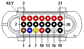
| |
Pin(s) |
Description |
Notes |
| |
1 |
Power ON/OFF |
OFF: +5 V, ON: Shorted to GND |
| |
2,5,8,11,13,14,17,19,20 |
GND |
Middle row - all, bottom row - pins 13, 9. |
| |
3,6,9,10,12,15,18,21 |
+5 V DC |
Top row - all, bottom row - pin 10. |
| |
4 |
+12 V DC |
|
| |
7 |
-12 V DC |
|
| |
16 |
Power Good |
+5 V if all voltages are stabilized |
Note: Some sources claimed that there is -5 V DC
on pin 9 (undocumented). This doesn't seem to be the case. I have measured this
on two different PSUs - one from Model 95 XP and one from Server 95A, and pin 9
is +5 V DC on both. In fact the entire pin row is +5 V (see above). I have
checked all the other pins as well, and -5 V is nowhere to be found. Further,
the entire row is connected together on the planar, so the -5 V on pin 9
"theory" doesn't make much sense from this point of view either, as the -5 V
output would just get shorted to the +5 V rail. I have also checked the Server
500 PSU (visually only) and the entire row is stuffed with red wires -
suggesting that it has +5 V on all of them too - including pin 9.
Primary Power Supply Voltages
If the voltages are correct, and the power supply fan runs, the power supply
is OK.
| -Lead Pin |
+Lead Pin |
Rail |
Vdc Min. |
Vdc Max. |
| 5 | 3 | +5 V DC | +3.7 | + 6.2 |
| 5 | 4 | +12 V DC | +9.0 | +15.0 |
| 5 | 7 | -12 V DC | -9.0 | -15.0 |
| B | D | +5 V DC | +3.7 | + 6.2 |
| B | A | +12 V DC | +9.0 | +15.0 |
Planar Power Supply Connector
AMP Metrimate 213516-1 Receptacle, 21 Position - Technical drawing;
In Stock
AMP Metrimate 213518-2 Plug Header, 21 Position, 43 Deg - Catalog sheet;
In Stock
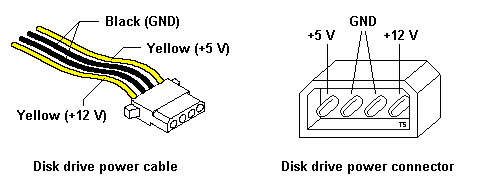
Wire Colors for Disk Drive Power Connector
IBM used Yellow-Black-Black-Yellow color scheme for disk drive power cables.
Checking Power Supply Voltages
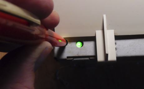
Some power supplies have a built-in test switch and LED on the side of the
power supply (there is no need to check voltages). On those power supplies,
disconnect the power supply from the system board, and remove all cables except
the power cord. Power-on the power supply and push the test button. If the LED
lights up, and the power supply fan runs, the power supply is OK.
On all other power supplies, short pin 1 to pin 2 and read the voltages on
the other pins. If the voltages are correct, and the power supply fan runs, the
power supply is OK.
Note: If you use a test button or short pins 1 and
2, the PSU will operate at a No-Load level, eg. the fan will be on low speed.
This very PSU tested green with nothing attached, but when plugged into a
system, the fan continuously searched high and low.
Ed. This is the 400 W PSU fan that was
continuously searching...
"But after I hooked a couple of hard disks on it, it was running fine for
> 20'."
Some repressed memories came up from the depths...
If the PSU is under no-load, then the fan will be operating at an unknown
low speed. PWM controllers spread out the pulses, so the slower the motor, the
farther apart the pulses. Amplitude stays at 12v. So it is very possible the
growly fan I heard during test was the fan controller "kicking" the fan over
with widely spread pulses.
This is interesting, as it illustrates the PSU fan control functions, which
up to now have been ignored (as long as it works). An experiment would be to
stick a 95A PSU on a Kill-A-Watt meter and an oscilloscope to watch the
waveform.
It would be more trouble than it's worth (except to be crowned "Alpha Geek")
to determine at what load the fan control goes from Low to High. In closing, it
is quite possible the PWM stuff needs to operate under load (how much, dunno)
before it can settle down.
Power Supply fails to start or shuts down
If the power supply shuts down, or appears to fail at power-on, you might
have one of the following problems:
- Too many devices are set to start instantly. Check Motor-Start Jumper.
- There are too many large-capacity devices installed.
- The Remote Maintenance Service Jumper
is not set correctly
- Faulty power switch or PSU
Power-On Request
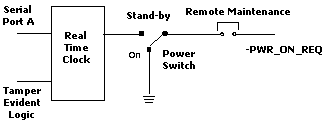
The power supply responds to a 'power-on request' signal to control the
power to the system. While this signal is inactive, the system is in the
standby mode. When the signal is active, the power supply is on and produces
its output voltage. The 'power-on request' signal is controlled by logic on the
system board, as represented in the following figure.
System Power-On Logic Diagram
Note: The Remote Maintenance
Jumper is present on the 85N and 95A planars It is a four pin header, surrounded
by a keyed white shroud. On the 95A/85N planars, it is in the upper left
corner of the planar (JMP6).
Sometimes, the system had a ServerGuard
adapter removed, but the Remote Maintenance Jumper is left open. The system
will not start, because it cannot get the Power-Good signal. Jumper the
pins1-2 and the system should power up.
Reliability
But to answer your question: the Mod. 95 PSU is not known for any particular
failure. There was a series of downlevel "Delta /US" made 400 Watt PSUs, which
failed after a short time - but these have blown themselves to hell already and
none of them has seen the year 1992.
The 95-PSU is rather complex inside. The main functions are distributed
among a number of smaller boards and tracking down failures isn't easy - except
you have blown and burned parts. In most cases however the failing components
are not that obvious to find.
The most common failure is the "no turning on" failure with the short
clicking noise and the high-pitch whistle afterwards. I don't know which
component causes this - and how to repair it.
Malfunctions that the PSU works for some time and then -by no obvious
reason- switches off (thermal problem) are only reported for *extremely* dirty
PSUs, mainly accompanied by blocked fans. After some time running the internal
protection circuit causes a "thermal shutdown" due to overheating. This could
be fixed in most cases by cleaning the thing and replacing the fan.
The commonly known problem with overheating and burning the stand-by part of
the PSU are not reported for the 95 PSU. It is no Magnetek / Italy made PSU...
:-)
High Quality (from Peter)
The thing is built like the proverbial brick outhouse.
A guy who (professionally) repairs switched power supplies looked into a
dead 95 PSU and was surprised as well. "How old did you say are the Mod.
95s?"
He was confused about the fact that an almost 10 year old machine had a PSU
with power factor correction... which might become standard "by law" next year
or in 2002 for the common lemming PCs.
If you have an AC wattmeter - plug in the PSU, shorten the "power switch
pin" and test out the idle wattage it takes. It is much lesser than the average
wattage taken from a 145 W chop-suey PSU from China or elsewhere. And the 95
PSU has 380 - 400 W output power...
Also a nice test is the "VDE 0100 Isolation Test" and the test for parasitic
currents over the input noise suppression filters. The 95 supply is also a
class of its own here. IBM wasn't cheap-skating on the PSUs.
Even the notorious Magnetek "Made in Italy" power supplies for the 35/56/76
are pretty good on their technical data and performance... apart from the
unlucky tendency to fry themselves to an early death. The concept was good -
the manufacturer wasn't (or the quality control).
Trying to Plug PSU Onto Planar Plug when case is Horizontal (from SuperVinx)
Someone gave me an 9585-ONG, formerly owned by a bank. The PSU was easy to
remove, but it was hard to reseat the power connectors between the PSU and the
planar while the system was horizontal. I've found that the 9585 must be in the
vertical position, all the way to the right on the mounting pins, in order to
seat with minimal effort.
Knob Assembly E-Clip
Missing E-Clips
How were all these PSUs missing E-Clips on the PSU knob?
From Charles:
The ijits that used these computers before don't realize that it's
the little e-clip that actually stops the screw knob from turning further.
If you crank on it hard enough, you WILL deform the clip, dislodging it from
the shaft, USUALLY the next time the PSU is unseated. It starts with a very
hard counterclockwise turn, and then you notice that that nothing is moving as
you turn the knob. Then when you pull -- pop! The e-clip finally gives way.
Charles Lasitter:
Does anyone know the correct E-clip size for the spring-loaded
screw shaft that we all know and love in the '95? I've had about a dozen too
many of them come flying apart and of course one of the E-clips takes its own
separate orbit.
E-Clip Type
The .670 is, as stated, the recess width which the e-clip has to fit. .553
is the outside diameter of the e-clip. So an e-clip with an outside dimension
of .553 (or a little less, hell, .450 should do) all the way up to .650 should
do.
The thread outer diameter is roughly .310". So the outside shaft diameter
will probably be a little larger, maybe .318 (standard fractional dimension,
IIRC).
The diameter of the part where the eclip rides should be .208 plus/minus
maybe .003". Thickness of the e-clip is .025".
Bob Watts:
You can go to NAPA and ask for part number: 1311. They are 32 ¢
each. I know they work because I installed them on my 8595 PSU. Problem taken
care of.
From the god Emperor of Microchannel:
Went to NAPA. Got a few 1311s. They are tight, Bob.
On a lark, I went to Ace Hardware. Ambled over to the fastener center.
Whipped open the Hillman External Retaining Rings box. Pulled out a 5/16th
Retaining Ring, 08236-00379 for a whopping 20 cents each.
They aren't as loose as the IBM e-clip, but you can turn then with your
fingers (the NAPA ones wouldn't).
95 PS vs 95A PSU
Just a little factoid - the 8595/9595 power supplies do not fully enclose
the well that the PSU knob's screw is in. This makes it possible for an e-clip
to pop off the shaft and fall into the PSU. On the 95A 400 W power supplies,
that well is solid all around the threaded end of the knob's shaft.
Air Deflector on 95A PSU

It starts on the left front corner of the PSU. 17.2cm/6 13/16ths" wide. The
air baffle extends towards the complex 8.7cm/3 1/4" inch from the outer edge of
the PSU. The air baffle has a maximum height of 3cm/1.5".
Although this air deflector was available as a separate part, the ones I
have are fastened with adhesive to the PSU case, and the outer side of the PSU
case is tack welded to the front and back faces. So you need to diddle around
and take off the inner PSU side.
Photo of the air baffle HERE.
Double Deck Complex Too Tall! (Type 1 w/ Cache & Type 3)
Lorenzo says:
The cache module installed prevents the power supply
from swinging out or in...
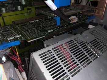
Ed. If you look closely to the left of the metal angle that surrounds the
PSU connector, you can see the planar power connector. I suppose you could lift
upwards on the Type 1 complex for the wee bit of clearance.
Tom adds:
The same thing applies to the double-deck T3 complex. I have to
push the complex up a bit before swinging the PSU out, otherwise the connector
shroud scrapes against the 2nd floor PCB...
Thoughts on Shipping
For shipping a PSU in a system, the whole thing should be bubble packed or
foam peanuts. I personally detest foam peanuts because those little dapper
devils get snapped into REALLY small bits. Those bits can then slip through the
PSU exhaust or the side louvers.
Once inside a PSU, you should open it to chase the bits out. Best to tape up
all vents with newspaper to keep the foam OUT.
I personally stay away from blown foam as the ONLY padding. It is rigid, and
IMHO transmits shock to the object inside. If the foamed object is then placed
in a larger box with foam peanuts or bubble pack or captive air, then any shock
is absorbed by the loose packing. YMMV.
For shipping a PSU by itself, I think a box with 4" of space around the PSU
leaves enough room for adequate bubble pack or captive air. Not a fan of a
foamed-in PSU in a box as the lone shipping container. YMMV.
In the end, we want to keep the ferrite transformer cores happy, Blown Transformer
Blown Transformer
Unfortunate victim is Frans Huizing:
One day, smoke came from the PSU and it promptly shut itself down.
I opened it up, (yes, I have the proper tool) and found 3 pieces of ferrite
loose in the supply: part of the core of a transformer. One piece had lodged
itself between what looks like a small regulator board and the main circuit
board where the short caused some physical damage to an area that is not used.
Yes, the 8A fuse was blown. However, on the little circuit board on the right
top corner are , what looks like, 3 resistors. The middle one has been fatally
damaged.
Now I come to my questions: Where can I find the schematic for
this supply.(Delta, SMP-400BB, EC3 D30618) And can you think of any reason
other than a manufacturing flaw why that xformer fell apart?
Dr Jim Shorney replies:
> Hey Jim, can this be cleaned up, a new transformer installed, and a new
resistor installed? I don't know of a source for schematics, and I know that
Delta will NOT just hand them out to a hardware hacker...
Jim says:
My advice: scrap it and send me the fan. When you see catastrophic
damage like that (melted and charred parts, things blown off the circuit
board), there is usually a fair amount of other damage lurking in the shadows.
You would end up throwing more parts at the thing than what it is worth.
> Why the hell would a core fail like this?
Powered ferrite cores aren't a terribly mechanically robust thing. Could
have been dropped. Or it could have been cracked by an intense high-frequency
spike from a nearby (or direct) lightning strike. (huh?)
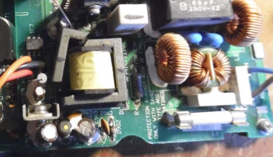
Finally dug out another 400 W from on the porch, and I heard a light
metallic tinkle when moving it. Not knowing what, I took it up to the operating
table today...
Took off the AMP planar connector... Took off the back wall. Unscrewed the
two screw / nut combinations from the AC socket. Slowly worked the nut holding
the ground cable to the PSU frame off.
Then I saw the "L" shaped light grey piece in the bottom. Faschizzle.
I do not see other damaged components, to me it looks like a physical shock
cracked this...
T1 Transformer Model
MP-??0B
SMT-????-390A
DET 9349-1 (date)
I could barely make out "SMT" on the transformer. Of course, the small print
faces a heatsink mounted FET.
|