|
DASD Storage Interface Specification Micro Channel (Rev. 2.2, Sep 1991)
Systems with DBA-ESDI
Direct Bus Attachment Pinout
Edge Connector Type
Straight Connector
Right Angle Connector
WD387 60MB Drive PCB
160MB DBA-ESDI PCB
Systems with DBA-ESDI
A list of systems equipped with the DBA-ESDI interface:
Direct Bus Attachment Pinout
The following table shows the signal assignment and pin numbering for the
2 x 36-pin hard drive edge connector. Side A of the connector is the top
(component side) and Side B is the bottom (solder side).
This is a subset of the standard Micro
Channel slot (16-bit).
| Pin | Dir | Signal | | Pin | Dir | Signal |
|---|
| A01 | O | -CD SETUP | B01 | O | A 15 |
| A02 | O | A 13 | B02 | O | A 14 |
| |
| A03 | — | Ground | B03 | — | Ground |
| A04 | O | A 11 | B04 | O | Reserved / 14.3 MHz OSC 1) |
| A05 | O | A 10 | B05 | — | Ground |
| A06 | O | A 09 | B06 | O | A 12 |
| A07 | O | +5 Vdc | B07 | O | -CMD |
| A08 | O | A 08 | B08 | I | -CD SFDBK |
| A09 | O | A 07 | B09 | — | Ground |
| A10 | O | A 06 | B10 | I/O | D 01 |
| A11 | — | Ground | B11 | I/O | D 03 |
| A12 | O | A 05 | B12 | I/O | D 04 |
| A13 | O | A 04 | B13 | — | Ground |
| A14 | O | A 03 | B14 | O | CHRESET |
| A15 | O | +5 Vdc | B15 | I/O | D 08 |
| A16 | O | A 02 | B16 | I/O | D 09 |
| A17 | O | A 01 | B17 | — | Ground |
| A18 | O | A 00 | B18 | I/O | D 12 |
| A19 | O | +12 Vdc | B19 | I/O | D 14 |
| A20 | O | -ADL | B20 | I/O | D 15 |
| A21 | I | -PREEMPT | B21 | — | Ground |
| A22 | I | -BURST | B22 | I/O | D 00 |
| A23 | O | +5 Vdc | B23 | I/O | D 02 |
| A24 | I | ARB 00 | B24 | I/O | D 05 |
| A25 | I | ARB 01 | B25 | — | Ground |
| A26 | I | ARB 02 | B26 | I/O | D 06 |
| A27 | — | +12 Vdc | B27 | I/O | D 07 |
| A28 | I | ARB 03 | B28 | I/O | D 10 |
| A29 | O | ARB/-GNT | B29 | — | Ground |
| A30 | O | –TC | B30 | I/O | D 11 |
| A31 | — | +5 Vdc | B31 | I/O | D 13 |
| A32 | O | -S0 | B32 | O | -SBHE |
| A33 | O | -S1 | B33 | — | Ground |
| A34 | O | M/-IO | B34 | I | -CD DS 16 |
| A35 | — | Ground | B35 | I | -IRQ 14 |
| A36 | I | CD CHRDY | B36 | — | Ground |
Notes:
1) The signal is marked as 14.3 MHz OSC in the Model 70 technical reference and
as "Reserved" in the P70 and 55 SX reference. It's not confirmed whether the
signal exists in all implementations.
There is a physical key between pins 2 and 3 (A02 and A03; B02 and B03). Not
all connectors have the key present.
Source:
Edge Connector Type
2x36-pin card edge connector, 2.54mm (0.100") pin pitch.
Through-hole; straight or right angle type.
Straight Connector
Used on the Model 50 HDD adapters, the
Model 70 drive riser, as well as some PS/55 machines.
AMP 650076-1
No datasheet found so far.
Right Angle Connector
Used on the Model 90 planar
(early samples only). The Japanese 5560 planar
also has a provision for a pair of these connectors.
Thomas & Betts HOLMBERG A8D36RA 29C
Thomas & Betts 1992 Full-Line Catalog (physical page 191 onwards)
A8 - Series Designator; A8 - 600 V DC
D36 - Number of contact pairs and readout; D - Double Readout, 36 - # contact pairs
RA - Termination style; Right angle dip solder tails
29 - Contact plating; 29 - Standard Plating (see datasheet for details)
C - Mounting style; C - Without mounting ears
Hirose Electronics A810056101
No datasheet found so far.
WD387 60MB PCB
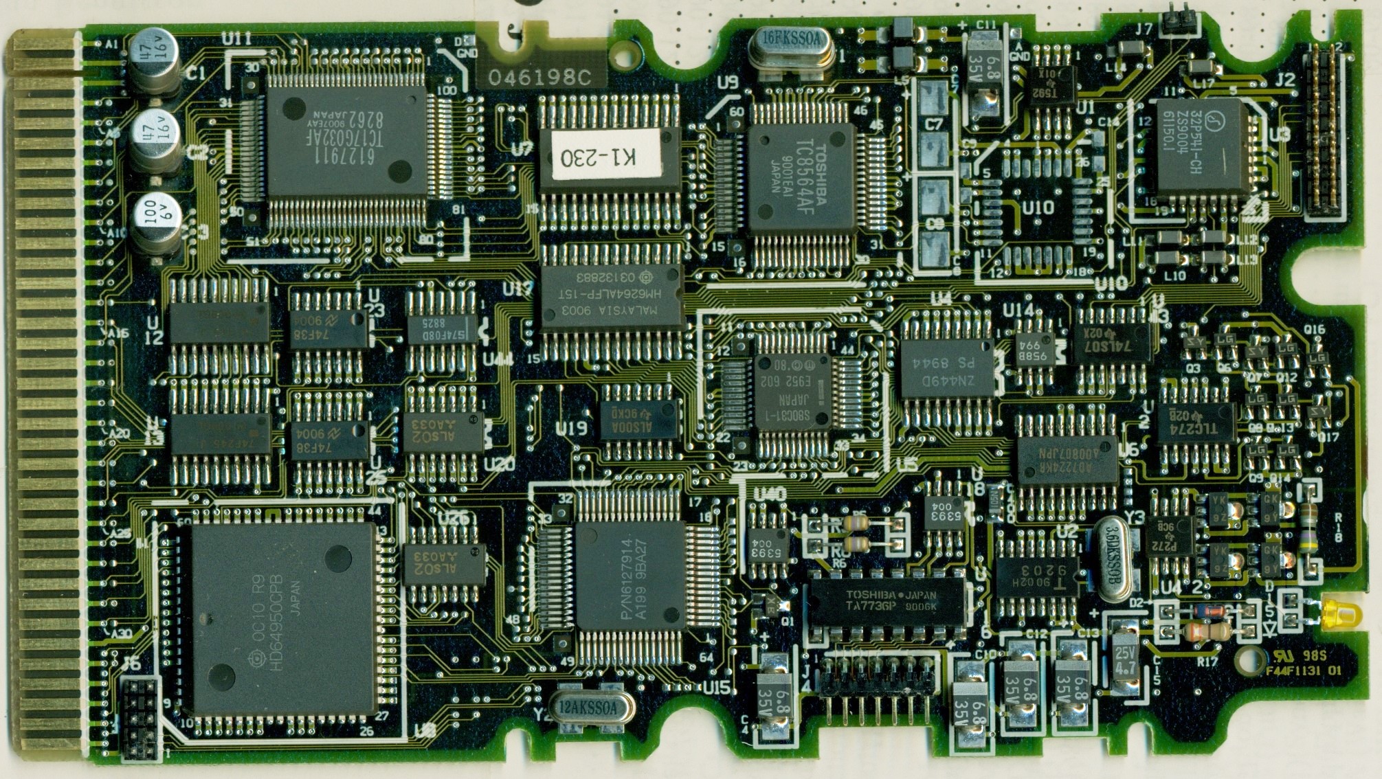
D15 Activity LED
J4 7x2-pin header (2 keys)
J7 2-pin header
J2 20-pin header
U3 SSI 32P541-CH Read Data Processor
U5 S80C31-1 MCU
U7 K1-230 microcode ROM?
U8 Hitachi HD64950CPB Hard Disk Ctrl.
|
U17 HM6264ALFP-15T
U9 TC8564AF
U11 TC17G032AF 6127911
U15 P/N 6127914
Y1 16KSS0A
Y2 12AKSS0A
Y3 3.6DKSS0B
|
160MB DBA-ESDI PCB 79F6370
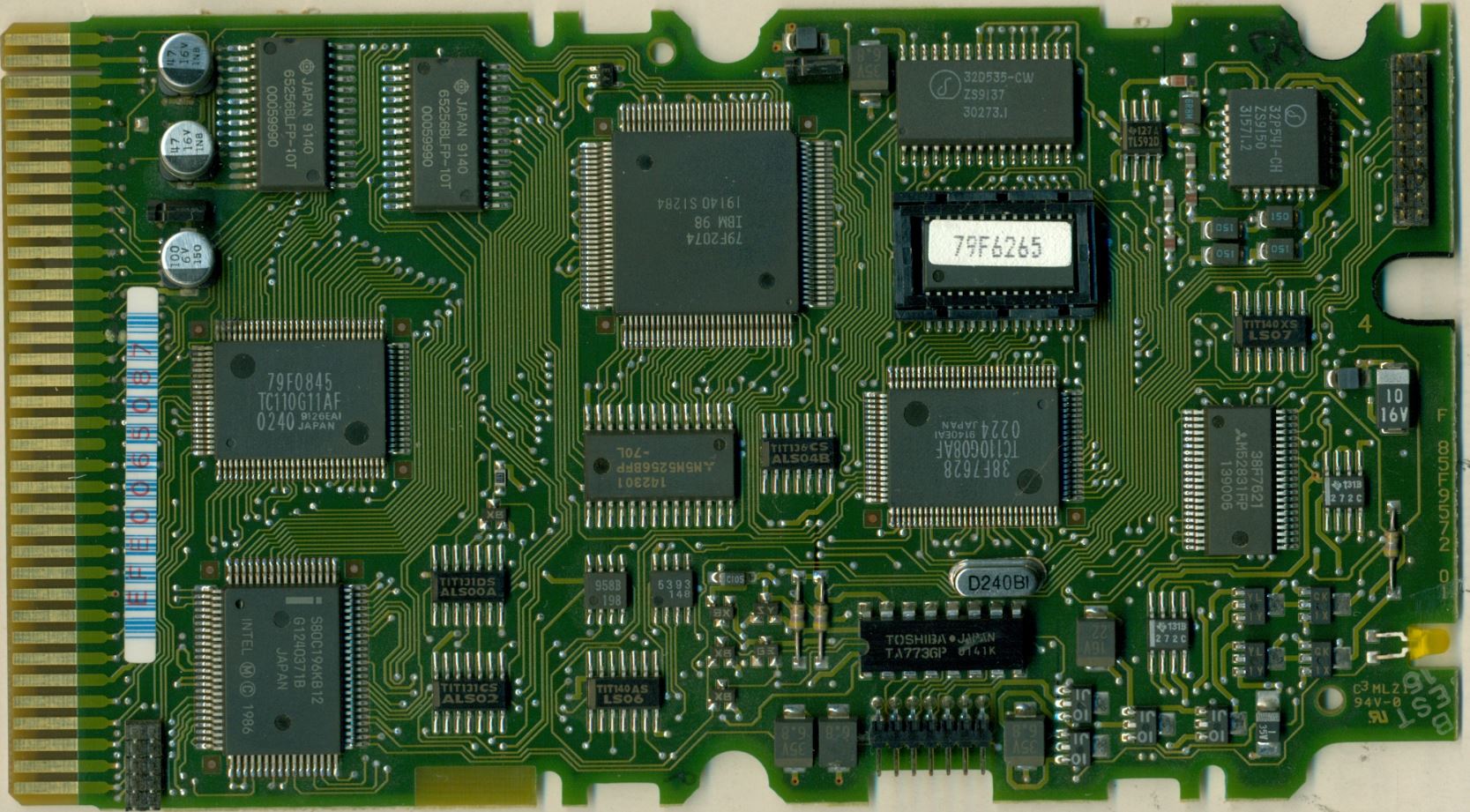
There are no reference designators silkscreened on the PCB.
Modifying 160MB SCSI Drive With ESDI PCB
Modifying a 160 MB SCSI Disk was only half way successful (took of the SCSI
PCB and hooked up the ESDI PCB from my bad 120 MB Drive). I can see the HD when
booting with the Refdisk, but I get all kinds of errors when trying to format
it.
The 160 operates with a different number of sectors IIRC. Only have the data
for the 80 and 160MB: 984 cylinders, 10 heads, 17 (80) and 34 (160) sectors. So
the 120 must have 26 sectors (25.5 arithmetically - but there are no half
cylinders ...). I think the 120MB controller cannot "fetch" a valid sector
start ... and therefore jumps out. The LLFORMAT routine does not go *that* deep
that it can write raw sectors on the media. That's usually the purpose of some
factory tools.
|