|
3070V150.zip Reference & Diagnostic Disk for 5530-S,T/5540-T/5550-S,T,V v1.50 (DOS/V)
3070V150R.zip Reference Disk for 5530-S,T/5540-T/5550-S,T,V v1.50 (DOS/V)
3070V150D.zip Diagnostic Disk for 5530-S,T/5540-T/5550-S,T,V v1.50 (DOS/V)
3070V136.zip Reference & Diagnostic Disk for 5530/5540/5545/5550/5570 v1.36 (JDOS)
40REF135.EXE Reference Disk for 5540-T v1.35 (JDOS)
General Information
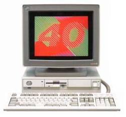
The 5541 was released after the 5550-S/T/V lineup. It doesn't have a
counterpart in the PS/2 series.
Reference Disks
Ref. ver. 1.00 to 1.36 are based on JDOS.
Ref. ver. >1.4x are based on DOS/V.
Ref. ver. 1.50 covers most 386 models such as 5550-S/T/V, 5570-T/V, 5540-T,
and 5530-T.
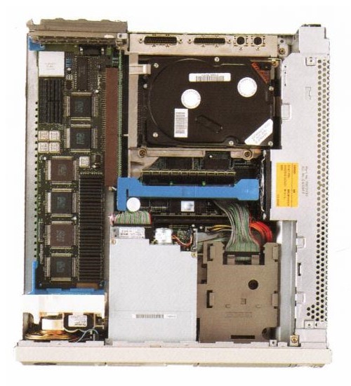
5540-T Planar (386DX 20 MHz)
Outline by Mr. Tahara (FIBMJ # 4 member). Edited by Major Tom.
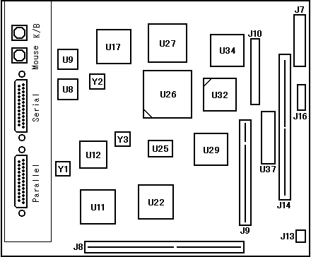
J7 Main 10-pin Power connector
J8 MCA Riser slot
J9 Memory Riser slot
J10 34-pin Floppy connector
J13 8-pin Power? connector (or SP?)
J14 72-pin SIMM socket
J16 7-pin Power? connector
U8 NS16550AV NS16550
U9 90X9298 8042
U11 35F3489 ADDR GA (buffer?)
U12 65F0082 EPP-3
U17 33F5838 I/O GA
|
U22 35F3489 DATA GA (buffer?)
U25 33F5946 CPU GA
U26 i80386DX CPU
U27 90X8134 DMA Controller
U29 79F1016 MEM GA
U32 80387 FPU?
U34 N828077AA FDD controller
U37 65F0155 BIOS EPROM
Y1 14.31818 MHz osc
Y2 24.000 MHz osc
Y3 40.000 MHz osc
|
Riser
3 MCA slots + DBA-ESDI connector.
Video
There's no VGA subsystem on the planar.
This machine can't take any Display Adapters other than the DA B-II
as its video sub-system.
Notice that the display adapter seen HERE
is not a DA B-II. It looks more like a DA II, III, or V from the
AVEC series, but it has 5 oscillators similar
to the DA B-II. It's currently unknown
whether this is the original DA B (BVEC) adapter or perhaps some uncommon
member of the AVEC family.
PS/55Z 5510-T, which is very similar to 5540, can be equipped with XGA.
Memory
| Capacity | P/N |
|---|
| 2MB | 23F3270, 59F9046, 79F2566 |
| 4MB | 79F2536 |
| 8MB | 79F2500 |
Hard Disk interface
Same as 8570 ESDI (more or less).
System Overview
|
|
One SIMM slot J14 is placed on the planar and additional 2 slots are
provided through SIMM riser card which goes to connector J9.
A bus riser for J8 connector has MCA card slots on the left side and
an ESDI HDD DB 2 connector is on the right side.
I/O connectors are placed as outline shows (Cable connectors are plugged in
vertically).
|
|