|
Content created by Sandy and Major Tom.
General Information
5560-W was the first desktop model with 486 class CPU. It was introduced
to the market on Oct. 1990 together with 5580-Y.
5560 is based on PS/2 Model 90
(8590/9590). It uses a similar, but not identical chassis. The planar has been
redesigned, and so were some of the processor boards. The main differences
are:
- No memory risers, SIMM sockets are directly on the planar (photo)
- Two extra 32-bit MCA slots in place of the memory riser connectors (2/3 length) (photo)
- No XGA video on the planar
- The second serial port is missing
- Power connectors are not card-edge type (more info, photo)
- The PSU can be swung out, similar to Model 95 (and even operated in that position) (photo)
- PC Speaker volume pot on the front panel (front panel, chassis)
- Provision for Op Panel (diagnostic LED display), not populated
(planar I/O, chassis stripped, chassis populated, LED display mockup, removable cover)
- More convenient SCSI adapter location, better cable routing, standard 50-pin header
- Other minor changes (cover slide bracket, cover lock, modified slot covers)
Photos: front, front #2, back, back PSU, short slot, inside, inside #2, -W1B w/ "kit W2B"
5560 Series Lineup (-W/N, original HERE)
| Model |
CPU |
Memory
(std/max) |
HDD |
Video |
| 5561-W08/W0B/W0C |
80486DX-25MHz |
4MB/32MB |
80-960MB |
PS/55 DA |
| 5561-W18/W1B |
80486SX-25MHz |
4MB/32MB |
80-960MB |
PS/55 DA |
| 5561-W28/WA8/W2B/WAB |
80486DX2-50MHz |
4/32MB
(8/32MB WAx) |
80-960MB |
PS/55 DA |
| 5561-N0B/NYB/NMB/NMY |
80486DX2-66MHz |
8/32MB
(16/32MB WMx) |
200-1GB |
PS/55 DA |
5560 Planar FRU P/N 79F2592, P/N 79F0084 or 79F5496
![Front [P]](/other/img/photo.gif)
![Back [P]](/other/img/photo.gif)

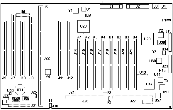
A1-4 SIMM sockets Bank A (J14-17)
B1-4 SIMM sockets Bank B (J18-J21)
BT1 Battery (CR2032)
F1 2 A fuse (keyboard/mouse 5 V)
F2 3 A fuse (floppy/DBA 5 V)
F3 5 A fuse (floppy/DBA 12 V)
J1 DB25 serial port
J2 Parallel port
J3 Mouse port
J4 Keyboard port
J5/22 Processor Complex slot
J6 Power-on password clear
J7 32-bit MCA slot w/ BVE
J8 32-bit MCA slot w/ AVE
J9-12 32-bit MCA slot
J13,23 Power Supply connectors
J14-21 72-pin SIMM socket
J24 Floppy connector
J25 Pads for Remote Power-ON Request
J26,27 Pads for DBA-ESDI connector
J28 Front Panel connector
J30 Fan connector (-12 V, GND)
|
J31 Pads for Op Panel connector
Y1 40.000 MHz osc (planar I/O bus?)
Y2 22.1148 MHz osc (UART)
Y3 32.768 KHz xtal (RTC)
Y4 14.318 MHz osc (adapters)
Y5 24.000 MHz osc (FDC)
TP1 Power Good test point
U1 65F1493 PAL
U6 "SPARE"
U20 57F2188 (int/KB/mouse) w/ bodge
U28 64F0942 (UART/parallel)
U30 µPD4464G-15 8Kx8 SRAM (NVRAM)
U34 Dallas DS1210 NV controller
U38 Dallas DS1285Q RTC/CMOS
U43 "SULL2" 1x9 solder pads (?)
U44 Pads for 74ALS38 (?)
U47 82077AA Floppy controller
U52 35F3798 PAL
U56 LM386 Audio op-amp (PC Speaker)
U58 Pads for 74ALS245 (op panel)
U57 "DSKBOOT" 64F3110 PAL
U60 "SPARE"
|
J7 pre-installed Japanese Display Adapter B-II or XGA-2
J12 pre-installed 2/3-length SCSI adapter
Important: The original electrolytic SMD capacitors
are prone to leaking! If your board is affected by this problem, you should
replace the capacitors and clean the board as soon as possible. Otherwise, the
leaking electrolyte will inevitably destroy the board!
All 21 SMD capacitors are of the same type - 33 µF 25 V (d = 6.3 mm).
It's safe to use 16 V parts. Polymer or tantalum capacitors can be used as
an alternative.
Important: The SIMM sockets on the planar are not
angled, which limits the SIMM height to approximately 28 mm. Most IBM modules
are ~25 mm tall, which leaves only some 3 mm of
clearance between the top edge of the module and the PSU. Make sure the
used modules are not too tall before you swing the PSU over the planar!
System Firmware (POST & BIOS)
Firmware stored on the Processor Complex.
J25 Remote Power-ON Request (not populated)
The unpopulated header J25 can be used to turn the system on (and off) from
an external source. This can be achieved by connecting pin 2 to ground
(either of the remaining pins). For this to work the Op Panel must be also
installed.
| Pin | Description |
|---|
| 1 | Ground |
| 2 | -Remote Power-ON Request |
| 3 | Ground |
Pin 2 is directly connected to pin 33 of the nearby Op Panel connector (J31,
also unpopulated) and pin 8? of the Front Panel connector (J28).
J28 Front Panel Connector
Looking at the plug (female) from the front:
|

|
| Pin |
Description |
Pin |
Description |
| 1 |
Volume Control (-) |
10 |
Volume Control (+) |
| 2 |
PWR LED (-) |
9 |
PWR LED (+) |
| 3 |
HD LED (+) |
8 |
PWR Switch (+) |
| 4 |
HD LED (-) |
7 |
Speaker (-) |
| 5 |
PWR Switch (-) |
6 |
Speaker (+) |
|
Note: The pin numbering is made up. The PCB has
the pins marked incorrectly on the silkscreen (duplicate numbers).
The volume pot is 10 KΩ (linear?) with a middle position detent.
J31 Op Panel Connector (not populated)
Provides similar functionality as the Model
95 Op Panel header, the pinout is different however. It was likely to be
used together with the Front Panel header (J28) but only with a smaller
(2x8-pin) connector populated (J28 and J31 partially overlap - both physically
and functionally).
| Pin |
Description |
Pin |
Description |
| 1 |
Ground |
2 |
Data 0 |
| 3 |
Ground |
4 |
Data 1 |
| 5 |
Ground |
6 |
Data 2 |
| 7 |
Ground |
8 |
Data 3 |
| 9 |
Ground |
10 |
Data 4 |
| 11 |
Ground |
12 |
Data 5 |
| 13 |
Ground |
14 |
Data 6 |
| 15 |
Ground |
16 |
Address 0 |
| 17 |
Ground |
18 |
Address 1 |
| 19 |
Ground |
20 |
-Write LED (low or high?) |
| 21 |
Ground |
22 |
-Write LED (low or high?) |
| 23 |
Ground |
24 |
+5 V |
| 25 |
Ground |
26 |
+5 V |
| 27 |
Ground |
28 |
+5 V |
| 29 |
-Power-ON Request |
30 |
+5 V |
| 31 |
Ground |
32 |
Volume Control (J28 pin 10) |
| 33 |
-Remote Power-ON Request |
34 |
Ground |
Note: Additional components must be populated for
the Op Panel to function. At the very least U58 (74ALS245) and possibly some
other.
Processor Complexes
60-W0x Complex (486DX 25 MHz)
60-W1x/W2x Complex (486SX 25 MHz / 486DX2 50 MHz)
N / DX2-66 Upgrade Type-B Complex (486DX2 66 MHz)
Model Types
As described HERE there are 4 types of 5560:
- 5561-W0x - 486DX-25: If you have filled all SIMM sockets with
8 MB SIMMs, you'll have enough time for cigarettes and a cup of coffee
(or two) until the machine finishes the memory count.
- 5561-W1x - 486SX-25: Faster memory count than -W0x.
- 5561-W2x - 486DX2-50: Most likely the same complex as in -W1x.
- 5561-Nxx - 486DX2-66: Supercharged 5560 with a Type-B DX2-66 upgrade platform.
5560-W
| Model |
5561 |
| W08, W0B, W0C |
W18, W1B, WYA, WYB |
W28, W2B, WA8, WAB |
| Processor |
486DX-25 |
486SX-25 |
486DX2-50 |
| RAM |
4MB |
4MB (70 ns) |
4MB (8MB for WAx) |
| VRAM |
1MB (PS/55 Display Adapter) B-2 |
Disk
Drives |
FDD |
3.5" x1 (1.44MB/720KB) |
| HDD |
Last digit of type code indicates HD capacity (8: 80MB, B: 160MB, C: 360MB) |
| Option Slots (free) |
32-bit full size x3, 32-bit half size x1 |
| Storage bays (free) |
2 |
| Dimension (mm) |
440 (W) x 430 (D) x 140 (H) |
| Weight (Kg) |
14 |
| AC Input |
AC 100-120V 50/60Hz, 215W (MAX) |
| Pre-installed OS |
None |
WYx: S/2 J2.0 & DOS J5.0 |
WAx: S/2 J2.0 & DOS J5.0 |
5560-N
Model 5560-N Brochure
| Model |
5561 |
| N0B |
NYB *1 |
NMB * |
NMY * |
| Processor |
i486DX2-66 |
| RAM |
8MB |
16MB (70 ns) |
| VRAM |
1MB (PS/55 Display Adapter) B-2? |
Disk
Drives |
FDD |
3.5" x1 (2.88MB/1.44MB/720KB) |
| HDD |
200MB |
| Option Slot (free) |
32-bit full size x3, 32-bit half size x1 |
32-bit full size x2, 32-bit half size x1 |
| Storage bays (free) |
2 |
| Dimension (mm) |
440 (W) x 430 (D) x 140 (H) |
| Weight (Kg) |
11.4 |
| AC Input |
AC 100-125V 50/60Hz, 194W (MAX) |
| Pre-installed OS |
None |
OS/2 J2.0 & DOS J5.0 |
OS/2 J2.0 & MCADAM |
OS/2 J2.0 & MCADAM |
*1 NYB : OS/2 model
*2 NMB : MCADAM/2 (CAD software) included. ASYNC TTL /Adapter is included.
*3 NMY : MCADAM/2 upgrade version. ASYNC TTL/Adapter is included.
Memory
8 x 72-pin SIMM sockets mounted directly on the planar.
Parity 8 MB/70 ns SIMMs are mandatory for -W1, -W2 and -N complex.
For W0 complex, 80 ns SIMMs are standard, and must be used in matched pair.
For W0/W1 models, reference ver. 1.11 is required to use more than 16 MB of RAM.
Video
No video on the planar.
32-bit BVE slot with PS/55 Display Adapter B-2 or XGA-2 installed.
32-bit AVE slot available.
SCSI Adapters
A 2/3-length 32-bit uncached SCSI /A adapter P/N 79F1140
was used for model -W0. The adapter has both the standard 50-pin header and the
IBM card edge connector.
A stock SCSI adapter for the -W1/W2 models is a 2/3-length 32-bit SCSI/A w/
cache and a standard 50-pin header, P/N 95F4488.
It uses the usual @8eff (32-bit with cache) ADF. SCSI microcode set is
64F4376/64F4377.
Model 5560-N was equipped with a short SCSI Adapter II/A (32-bit) with 512
KB cache (marked as 06G6760 in sales leaflets, and I think it's either
35G2818 or 07G3063).
Inner View
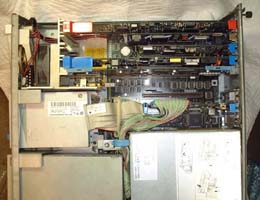
Photos below are inner view of my 5561-W1B with Type-B Upgrade processor
complex installed. Half-sized cached SCSI A/32 with 50-pin header was replaced
with a short caching SCSI 32/A with new microcode set.
You can see an AMD 5x86-133 CPU on an interposer with a low-profile
heatsink. The CPU runs at 160 MHz (internal). No CPU fan, but the front fan
blows a fresh air over the heatsink.
Picture #1 - Adapters (top to bottom)
|

|
#6: Madge Smart Ringnode MC32
#5: XGA2
#4: ACPA
#3: Intel Fax/Modem Adapter
Complex: DX2/66 Upgrade Type-B
w/ interposer - closeup 1, closeup 2
#2: (empty)
#1: Short Cached SCSI (w/ new microcode)
|
|
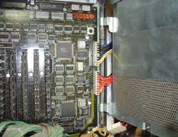
Picture #2 - SIMMs and Power Connectors
|

|
You can pull the PSU forward and then swing it to right side, similar to Model 95.
Notice how different the power connections are when compared to Model 90.
Tall SIMMs are not good for 5560. There isn't much space
between the SIMM slots and the PSU (~28 mm).
|
Sandy's 5561-W1x (upgraded with 60-N complex)
64 MB of RAM, BIOS modified N complex with 80 MHz osc, AMD 5x86 running x4
speed, ATI-GUP, Madge Ringnode MC32, Genuine IBM SCSI A/32 with cache, 650 MB
+ 1 GB hard drive, Hitachi 2x CD-ROM without bezel.
|