|
REF346.EXE Reference Disk for Reply Systems
225-32.EXE Update program for Reply System 32
T226.DAT Upgrade Reply 32 for DX4/100 support
Specifications
Features
- Modular design - user-upgradeable "TurboProcessor" modules
- "five-by-five" architecture - 5 full-length MCA slots and 5 drive bays
This applies to the Model 16 as well.
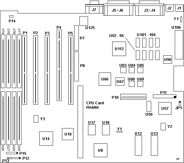
Reply 32 Planar

F1 Fuse
J1 Keyboard
J2 Mouse
J3,4 LPT1,2
J5,6 Serial 1,2
J7 Video
JP1 Clear Password?
P1-3,5 32 bit MCA slots
P4 32 bit AVE MCA slot
P6,7 DBA-ESDI header
P10 Power header (AT style plugs)
P11 Floppy
P12 Unk and unused.
P13 Battery 6v like P75
P14 Speaker
P15 Front panel LEDs
U8 Chips F82C325A Data Buffer Controller
U12 BIOS Odd
U13 BIOS Even
U14 Chips F82C322A Memory Controller
U16 Chips F82C223 DMA controller
|
U17 Chips F82C321A MCA Controller
U18 F82C226 Non-Volatile RAM
U26-29,74-77 30 pin SIMM sockets
U56 Toshiba TC5565AFL-12
U57 82077AA-1 Floppy controller
U66 Chips P82C575 MCA Bus Interface
U67 TI TL16C550AFN
U68 50.350 MHz osc
U69 40.000 MHz osc
U83 65.000 MHz osc
U84 28.322 MHz osc
U85 1.8432 MHz osc
U92-95,101-105 Via V53C864K80L
U96 TI TL16C550AFN
U106 Chips KB Controller BIOS
U112 Chips F82C452A Super VGA controller
U125 Bt471KPJ80 RAMDAC
Y1 32.8 khz xtal (whatever the timer needs)
Y2 24.00 MHz xtal
Y3 14.31818 MHz xtal
|
Memory Controller 82C322
Supports 256 K-1 M of DRAM, Shadow RAM, Supports up to 16 MB, Wait state
programming
DMA controller 82C223
Performs DMA operations
8 independent DMA channels
Performs extended mode operations
Memory addressing capacity of 16 MB
Performs DMA serial operations
Provides virtual DMA on channel 0 and channel 4
82C452 Super V.G.A. video controller
Data Buffer Controller 82C325
Bus Conversion and Bus Swapping functions
Parity genertion and error checking in the DRAM
Contains MCA POS registers
82C226 Non-Volatile RAM
Real Time Clock, DMA Controller, Interrupt Controller
82C226
Two 8259 interrupt controllers
8254 compatible timer
Watchdog timer
Real Time Clock compatible with the MC146818
114 byte CMOS RAM
Parallel port controller
MCA Controller 82C321
MCA compatibility
Memory timing
32-bit - 16-bit bus converter
Clear CMOS
JP1
CMOS normal pins 1 & 2 closed
CMOS clear pins 2 & 3 closed
DRAM Configuration (to be tested, 09 Aug 2003)
  Size   Bank 0        Bank 1
  1MB    (4) 256K x 9  NONE
  2MB    (4) 256K x 9  (4) 256K x 9
  4MB    (4) 1M x 9    NONE
  5MB    (4) 256K x 9  (4) 1M x 9
  8MB    (4) 1M x 9    (4) 1M x 9
  16MB   (4) 4M x 9    NONE
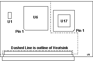
486 CPU Module

|
U1 66.6667 MHz osc
U6 486DX-33
U17 15x15 PGA socket Weitek?
|
Heatsink (if it isn't missing) is made from 1/8th inch black anodized
aluminum.
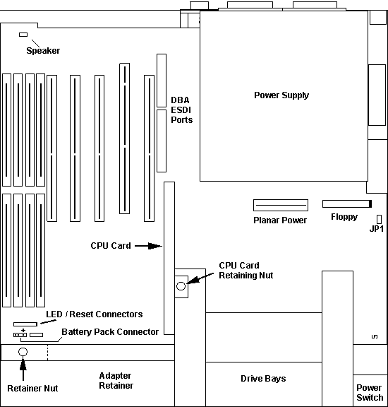
Interior Case Layout

Remove the Case
Just like the 8570, unscrew the three knurled screws at the back (they will
come free, they aren't captive), and slap and pull the top cover to the front.
After about 2 inches of forward travel, you can lift the cover up.
Remove the Planar
As you'd expect from a bunch of former IBM'ers, it's fairly easy. Pull all
adapters. Unplug the speaker, LED/Reset Switch Header, battery header, pull the
CPU card, remove the floppy and power plugs, pull the edgecard off the DBA-ESDI
drive (leave the tape connector headers in the board sockets).
Remove the screws holding the planar in. To my surprise, ALL planar screws
ARE reachable with the PSU and hard drive in place. Remove the (outside)
mounting posts from the video, both serial and both parallel ports.
Now push the planar in from the port cutouts so they are inside the case.
Slowly pull the planar out of the case away from the power supply. Keep the
angle low because the BIOS chips have to fit in a cutout in the drive support
structure.
The case is very well made for being a clone-tyoe.
CMOS Battery
Uses a Tadiran TL-5293/W, 6v lithium.
Floppy Drive
The floppy in a Reply 32 is a TEAC FD-235HF. Has separate signal and power
cables. Uses the clone mini 4 pin power plug. 34 pin signal plug.
Note: The floppy header is poorly marked. Pin 1 of
the floppy cable is towards the outer side of the system.
Floppy Jumper Settings

Install / Remove Full Length Adapters
Open the case. At the front. notice the knurled nut? Unscrew it. Pull the
"hood" up, when it clears the post, pull the hood towards the rear until it
detaches from the case. There are NO further screws or other fastening devices
holding it in. Now full length adapters are free to be handled without
interference.
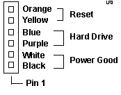
LED / Reset Connectors (P15) Pinout
Note: When removing the LED/Switch assembly from
the front of the case, the screw that has the grounding conductor attached is
longer than the other screws. It has to be long enough for the terminal ring
and nut to fit on it as well.

Note: When attaching the LED/Switch header, note
that two positions are empty on the plug. The two empty positions go to the
left of the pins. The black wire goes to Pin 1 on P15.
Planar Power
Uses the same two rectangular plugs like AT class systems. Remember, when
plugging in the headers, the black wires on the two plugs are to the center of
the header.
Power Supply
Power supply is Delta Electronics SMP-200JB, 199.1 W
100-120 V @ 6 A / 200-240 V @ 3.5 A, 47-63 Hz
Important: The PSU is not autoranging! To switch
between 115 V and 230 V, you MUST use the slider switch between the AC plugs
at the rear of the case!
+5 V @ 22 A
-5 V @ 0.3 A
+12 V @ 7 A
-12 V @ 0.3 A
Load Resistor?
On the interior front side of each Reply 32 is a aluminum cased, finned
power resistor. There are three 5.25" drive power connectors in the Reply 32,
two are only long enough to reach the internal 5.25" bays in front of the case
(opposite the PSU). The third 5.25" power lead reaches over to the front, right
side of the case and connects to a connector that goes to the power
resistor.
Dale RH-25, 25 V, 30 ohm, 1%.
                                 ____      Load Resistor
         ------- +12 V ---------|    |---------/\/\/\----|
 PSU     -------- GND ----------|    |-------------------|
         -----------------------|    |
         -----------------------|____|
I though that stuff like this vanished with the XT...
AdapterId 06FB5h "Reply On-Board Serial/Parallel
Adapter"
Serial/LPT Connector
Selects serial port, ports 2 - 8 & Parallel port,
ports 2 - 3
<"Serial 2 :
LPT 2"> (io 02F8h-02FFh 0378h-037Fh int 3 7), Ser3 -LPT2 (3220-3227
378-037F 3 7), Ser4 -LPT2 (3228-322f 378-37F 3 7), Ser5 -LPT2 (4220-4227
378-37F 3 7), Ser6 -LPT2 (4228-422f 378-37F 3 7), Ser7 -LPT2 (5220-5228 378-37F
3 7), Ser8 -LPT 2 (5228-522f 378-37F 3 7)
Ser2 -LPT 3 (2F8-2FF 278-27F 3 7),
Ser3 -LPT 3 (3220-3227 278-27F 3 7), Ser4 -LPT3 (3228-322f 278-27F 3 7),
Ser5 -LPT 3 (4220-4227 278-27F 3 7), Ser6 -LPT 3 (4228-422f 278-27F 3 7),
Ser7 -LPT3 (5220-5228 278h-27F 3 7), Ser8 -LPT3 (5228-522f 278-27F 3 7)
Ser2 -LPT OFF (2F8-02FF 3), Ser3
-LPT OFF (3220-3227 3), Ser4 -LPT OFF (3228-322f 3), Ser5 -LPT OFF (4220-4227
3), Ser6 -LPT OFF (4228-422f 3), Ser7 -LPT OFF (5220-5228 3), Ser8 -LPT OFF
(5228-522f 3), Serial OFF : LPT OFF
|