|
85, 95, and 3511 Common Devices (Installing drives, memory etc.)
Opening and closing the case
Operator Panel Information
95 XP Planar
Board Revisions and P/Ns
System Firmware
95A Ports
95A Operator Panel
J4 Remote Power-ON Request
SIMM Connector Versions
Supported MCA Features
Planar Limitations?
95 XP 486 Planar FRU P/N 33F5717, different P/Ns
DU1 and
U55 are present on some boards but
unpopulated on other - see below. Purpose currently
unknown.
U22 8Kx8 SRAM (NVRAM)
SRM2264LC-12
(alt) or
Sony CXK5864BP-12L
Board Revisions and P/Ns
All 1S1P boards use the same FRU P/N - 33F5717. There are however multiple
different board revisions, from different sources, with different P/Ns:
- 91F7441 (no U55 pads, w/ DU1, early, Greenock)
- 84F8309 (w/ U55, w/ DU1)
- 04G3888? (w/o U55, w/o DU1)
- 04G3863 (w/o U55, w/o DU1)
- 92F1480?
Early 1S1P planars (P/N 91F7441) have a slightly different layout and lack
provision for U55-58. Three DIP resistor networks
between slots 1 and 2 are also missing. Additionally, these boards come with
quite a few bodge wires (8 total - 4 near the I/O ports, 1 next to U26, 1 near
Slot 1/RN2, and 2 at the underside of Slot 2).
System Firmware (POST & BIOS)
Firmware stored on the Processor Complex.
8595 / 9595 Ports

COM DB25 serial port capable of 345K
LPT is standard parallel port
The parallel port is NOT
ExpressPrint capable.
8595 / 9595 Operator Panel
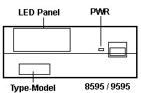
On the earliest 8595s, the power button has no shutter and is surrounded by
a raised lip. On later models, the power button is covered with a shutter.
More information about the operator panel can be found
HERE.
J4 Remote Power-ON Request
The J4 header can be used to turn the system on and off from an external
source (i.e. a modem card). This can be achieved by connecting pin 2 to ground
(either of the remaining pins). It will only work if the
hidden switch SW1 on the Op
Panel has been pressed to enable the Remote Power-ON feature.
| Pin | Description |
|---|
| 1 | Ground |
| 2 | -Remote Power-ON Request |
| 3 | Ground |
Pin 2 is directly connected to pin 29 of the nearby Op Panel connector (J3).
SIMM Connector Versions (Grey or Green)
8MB ECC SIMMs from IBM (Option P/N 92G7208, FRU P/N 92F0098) may not fit
properly in the SIMM connectors of some systems.
The following system types and models are potentially affected:
8595 - all models
9595 - model 0LF (see note below)
Early production 8595 system boards have gray plastic SIMM connectors which
physically interfere with the installation of the referenced 8 MB ECC SIMM.
Later production system boards used a green SIMM connector, which is
compatible with the larger SIMMs. Many earlier systems, which have been serviced
in the past 18 months, could have the later production system board (green SIMM
connectors) already installed.
All system boards with green memory SIMM connectors, regardless of model
number or processor upgrade are not affected.
Note: 9595 model 0LF is the only model
of 9595 to use the 8595 system board, FRU P/N 92F0270, (identified by a single
serial and a single parallel port).
Supported MCA Features
Source: PS/2 Models 95 XP 486, 90 XP 486, 55LS and P75 486 Fundamentals (page 36 physical)
All of the 32-bit Micro Channel slots on the IBM PS/2 Model 90 XP 486 and
Model 95 XP 486 systems are full 32-bit implementations of the Micro Channel
Architecture. In addition to the basic Micro Channel features the IBM PS/2
Model 90 XP 486 and Model 95 XP 486 systems support the following enhancements
to the Micro Channel architecture that were announced in November 1989:
- Data parity - This is supported on the Micro Channel for peer-to-peer
transfers between supporting adapters.
- Address parity - This is supported on the Micro Channel for peer-to-peer
transfers between supporting adapters.
- Streaming data procedure - This is supported up to 80 MBps using a
64 bit data path and a 100 ns cycle. It is supported on the Micro Channel for
peer-to-peer transfers between supporting adapters.
These three new Micro Channel features are implemented on the planar boards
of the Model 90 XP 486 and Model 95 XP 486 systems.
Planar Limitations?
Important: The information below is known to be
inaccurate. It's retained here solely for historical context. Please refer to
the editor's note for corrections.
From Peter (source):
The 8595 planar is "stage 3" and does not support the "stage 4"
"synchrostream mode", which is turned off then. It supports the normal 64-bits
burst mode with up to 40 MB/s. So a Type 4 platform will be significantly
slower in an old 8595-type planar than in a Server 95A planar (the one with the
two serial and two parallel ports). The planar controller on the "single-LPT"
planars does not return the proper values on trying to start up the
SynchroStream - therefore it is not used. The only advantage left over is the
faster CPU and higher calculation data throughput - and the ability to run
Pentium software (if required). The overall performance is of course higher
compared with e.g. the DX-50 platform - but it does not even come close to the
values achieved with the same processor card in the 9595A "double LPT"-planar.
At least not in a cumulative / weighted application which includes combined
calculation and I/O traffic loads.
Ed. There is no such thing as a "synchrostream
mode". The SynchroStream Controller on
the T4 complex supports
40 MB/s data
streaming - but the same is true for the T3
complex that was shipped exclusively with the 1S1P planar. Also, the
64-bit streaming
mode has a theoretical bandwidth of 80 MB/s instead of 40 MB/s and it's
certainly not a "normal" transfer mode in the PS/2 world - it's only used by a
very few late development cards. Further, according to the Tech. Ref. (see
MCA Features above) the bus on all Model 90/95
planars should be compatible with streaming transfers up 80 MB/s - at least
between the adapters, as no 90/95 processor complex ever supported the 80 MB/s
mode. The bus on the 2S2P planar might actually support the 50 ns 160 MB/s
streaming (as mentioned in the INF
Reference), but to our knowledge no PS/2 adapters or complexes ever
implemented this mode. So, to sum things up, there should be
no performance difference between the two Model 95
planars (aside from the faster parallel port on the 2S2P board).
|