|
The Problem
The Action
What you need to do
Results & Feedback
This page is based on Peter Wendt's work (original HERE). Edited by Major Tom.
The Problem
You have either a PS/2
Model 25-286,
30-286,
55 SX/SL, or
65 SX which comes up with a "165 configuration
error", and fails to retain the system configuration when power-cycled. Well,
these machines have the dreaded Dallas
DS1287 "all in one" Real Time Clock
(RTC) and NVRAM chip with integrated xtal and battery. Now the battery is dead,
configuration is lost after relatively short time again and you get error codes
constantly. A really new, fresh and unused chip is hard to get. Even its
successor DS12887 is pretty hard
to get and darn expensive. At that point you wish you could simply add an
external battery. But you can't. There are no provisions for one. Not yet
anyway...
Ed. This same method is usable for other
non-IBM systems that use one of the all-in-one Dallas RTC modules.
The Action
Have a look at the graphics below. Basically the DS1287 is a
DS1285 chip, where the pins for the xtal-connection and the battery are bent
upwards. Then the battery and xtal are placed atop of the chip, connected to
the pins and everything is covered with a pretty rigid protective compound.
See the x-ray image below to get better idea of how the internals of the module are laid out.
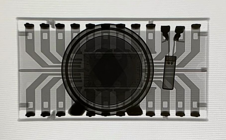
X-ray of the Dallas DS1387 module (pin 1 on the top right)
(presented by Dave from EEVBlog, x-rayed by CPU Galaxy)
The DS1387 is the same chip with an additional integrated 4K SRAM.
All described modifications apply to this chip as well.
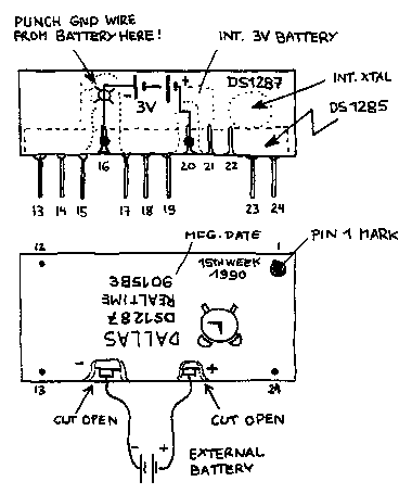
What you need to do
- Remove the Dallas chip from the machine if it's socketed.
Sadly many PS/2s have the Dallas chip soldered directly to the planar.
- Use a Dremel or a metal saw to make a vertical at around pin 16, until you
reach the metal pin itself (be careful not to break the pin).
- Repeat the procedure with pin 20.
- Scratch off the sealing compound around the pins, particularly at pin 16
towards the top.
- Use a watchmaker screwdriver or a nail to break the connection from pin 16
to the negative terminal of the battery.
Note:
Don't be afraid, this chip is really hard to damage. If you have a multimeter
test the voltage on pins 16 and 20 before and after. Before it may read
anything from some 100mV up to 3V (where you should ask yourself *why*
you wish to modify this chip?) and after it must be 0 (zero) latest
after 5 seconds of measuring.
When you get a 0V reading, you have successfully disconnected the battery.
- Solder two wires of appropriate length to pins 16 and 20.
- Solder a "3 Volt Cell" to the wires.
Watch the polarity! Pin 16 is GND (-), pin 20 is (+).
Notes:
This abstract "3 Volt Cell" could be either a battery pack [2 AA or AAA]
or a 3V lithium coin-cell installed in a battery holder.
Don't ever solder directly on a coin-style Li-Cell!
It won't do it no good and may result in early death of that part due to
excessive internal heating. Most likely you won't get a wire soldered properly
to it. The case is usually pretty much "solder-resistive" because of the
anti-corrosion plating.
Don't use rechargeable batteries! These are intended
for short-term use with strong charge and discharge intervals - not for
long-term storage with a comparatively small discharge rate. The daily
self-discharge rate on some rechargeables is higher than the current taken by
the RTC.
- Optionally use some hot glue to cover the dremeled pins and fix the battery
to the module.
Note:
The "appropriate length" bit regarding the wires refers on that situation
where you use a 2-cell battery holder and want to place it elsewhere inside
the computer - further away from the DS1287 chip itself.
- Reinstall the reworked chip in the machine - watch out for proper
alignment and position of pin 1 - and reconfigure your PS/2 using the corresponding
Reference Diskette. Should work like a charm.
Results & Feedback
Moritz Hoffmann from Germany shared his results:
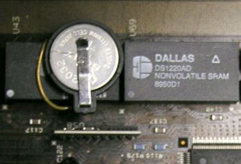
Reworked chip inside a Model 65SX
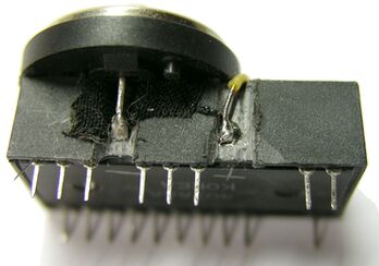
Side view of modded chip. Note the battery holder!
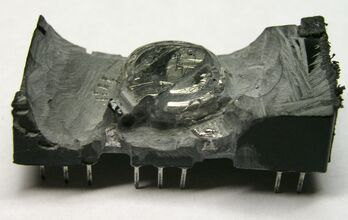
Curiosity killed that cat. After the dust cleared...
Above pictures © 2006 by Moritz Hoffmann & his father.
Chris reported the following:
My old computer has been out of action for months, but this week I got
it going again by following the instructions on your webpage "Reworking
the DS1287 RTC chip".
Without that webpage, I would never have thought of repairing it like
that!
So you have my thanks and gratitude for putting that idea on the web.
(Incidentally, my computer is an Compaq 386N, which seems to date from
about 1990).
With thanks,
Chris.
Gary Jay in Ohio, USA reported the following:
Hi Peter...just thought I would let you know that
I got the DS1287 reworking on my first try!
I used an iron file that was about the exact width I needed and just
slowly went back and forth about 50 times until I saw the metal and
then used sandpaper the rest of the way.
Soldered and used a CR2032 battery with holder on top of the 1287.
Worked like a charm and would like to thank you and I am very grateful
I stumbled on your web site. I could not have gotten my Compaq DeskPro
286e back to clock life back without you! Regards, Gary
Emmanuel Da Piedade from France wrote me:
Hi Peter,
My name's Emmanuel, and I live near Paris in France.
I just want to tell you that I successfully used your DS1287 rework How-to.
You did a great job! Thank you! My IBM PS/1 m2011 works fine now!
You can see the result here (sorry, the text is in french):
here
Best Regards
Emmanuel
D. Howe, USA did the modification for his Dell 4100 computer, he reports:
Dear Peter,
I bought an old DELL 4100 computer about 7 years ago to play with because it
had an 80486DX4 chip in it. Then circumstances kept me from working with it
until now...the computer spending all this time in my garage. A couple weeks
ago when I finally got around to hooking it up...I discovered that the RTC chip
was dead.
Can you imagine my amazement and relief when I discovered your web site
describing the DS1287 rework process.
I used a medium sized flat file...a little less thick than the distance
between two pins...to file down to the two battery pins. I soldered a #22 solid
wire to each of the battery holder pins, then glued the holder to the DS1287
case using model airplane plastic cement. Attached the two wires to the exposed
pins and put the new lithium cell in the holder. Voila!
It works like a champ!
For anyone who attempts this mod... don't make my
mistake with the plastic glue. It sets too fast!...less than 15 seconds. Go
with the hot glue.
So...Peter...Thank you very much for putting this mod on your web site. I
appreciate it greatly.
With regards, D. Howe
Kalamazoo, Michigan, U.S.A.


Above 2 pictures © 2009 by D. Howe.
From William R. Walsh (original here):
If you follow the procedure described here, you'll probably do fine. Unless
of course you're like me and have more bad luck than you should when things
come down to the wire. The suggested implement to open these modules is a
Dremel tool. My Dremel tool--while a nice piece of equipment--spins at a
minimum of 5,000 RPM and was all too happy to open not only the potting
compound, but also the IC and in some cases, even the battery. I went through
five or six DS1287 modules before deciding that this method wasn't going to
work for me.
You will remember that I said something about a judicious application of
violence on the Model 25 batteries page ...
maybe I was getting a little carried away?
In any case, I turned to hand tools...I started with a sharp knife to make
the initial cuts and followed them up with by running the jaws of a needle nose
pliers into the cuts. The serrations in the jaws slowly dug deeper into the
potting resin and it wasn't too long before I saw the first battery contact.
For the second module I reworked, I did all of the work using a moderately
sized side cutters. This was quicker, although it made more of a mess and the
module didn't solder as nicely as the first. Whatever you do, handle the pins
on the module carefully. They have a tendency to bend when you aren't looking.
If you fix the bent pins too many times, they will break off. That usually ends
the experiment before you've even arrived at the part where the module is
exposed to the blistering heat of your soldering iron.
When you get past the potting compound and into the terminals, clear away
just enough potting resin to catch the negative battery terminal heading up to
the top of the package. When you've exposed this, punch through it with a nail,
awl or similarly sharp device. You want to be sure the battery is disconnected,
so double-check with a voltmeter. It won't do you any good to "charge" the
depleted button cell. It could start a fire, explode or just make a smelly
mess.
Soldering was the next big thing. I didn't feel up to soldering a CR2032
holder onto the module (and there's the question of finding one in stores
around here), so I purchased a triple-A battery holder and some batteries from
Radio Shack. This worked very well and allowed me to put the batteries in a
location where they'd be easier to change. In the event of a battery failure,
the holder can be placed away from the sensitive planar or other circuitry.
To give the newly reworked module some more strength, I used hot glue to
secure the battery leads and holder inside the system unit.
Finished Results
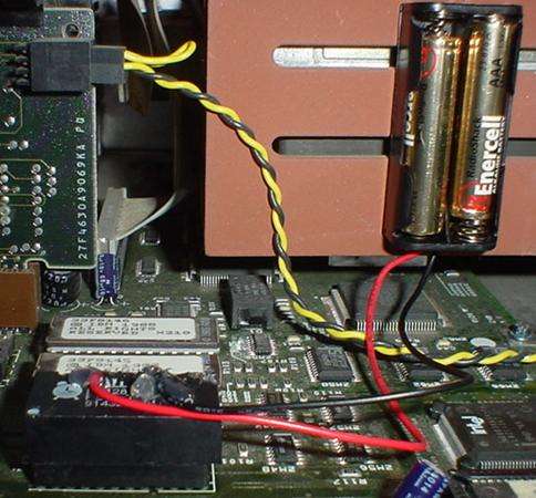
The above picture shows a reworked module installed in a PS/2 Model 55SX. I
couldn't get far enough away from the planar with my batteries, but I'll keep
an eye on them periodically.
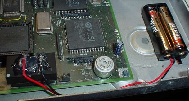
This picture shows the second module I reworked in a Model 30-286. While
this one didn't solder as nicely (and had to be resoldered once when the
positive lead came unglued!) the battery holder is safely away from the planar
and other parts.
If you do something like this, try to situate the batteries far away from
the system board/planar or other parts inside the computer. Also be sure to use
high quality name brand batteries, such as Energizer, Ray-O-Vac or Duracell. Be
sure not to use rechargeable batteries.
Next up--when the depletion of the internal battery happens--will be rework
tips for the "other" Dallas modules, such as the DS1387 Real Time RAMified
module, as well as the 1287 variant that is used in my EISA Compaq DeskPro
computers. There exists no modern day replacement for these, so re-energizing
them is the only option.
|