Author: Bo Ericsson
Source: Dr. Dobb's Journal, April 1990 Page 75-76, 77-79
An integral part of IBM's PS/2 announcement in April 1987 was the video
graphics array (VGA) system. Based on the architecture of the enhanced graphics
adapter (EGA), the VGA offered extended resolutions and a new 256-color video
mode. Since that time, the VGA has grown in importance and is today an
established PC video standard. As a matter of fact, all "old" video standards -
the monochrome display adapter (MDA), color graphics adapter (CGA), Hercules
Graphics Adapter, and EGA - are quickly losing ground to the VGA.
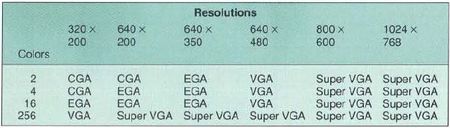
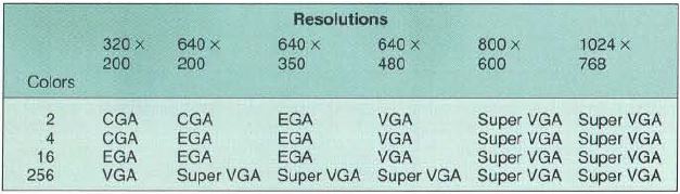
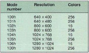
Figure 1: PC graphics resolutions and colors
There are several reasons for the VGA's success. For one thing, the new VGA
resolutions (see Figure 1), together with lower-priced multi-frequency
monitors, have made the VGA a more attractive solution than previous standards.
Also, a multitude of VGA offerings and fierce competition have made a baseline
VGA an economically attractive choice.
As a matter of fact, competition in the VGA marketplace not only has driven
the prices of VGA boards to the bottom, but has pushed up the features and
capabilities of these boards. Virtually all VGA controllers available today are
compatible down to the register level with the IBM VGA, and almost all of them
implement some extensions to the IBM VGA.
The term "SuperVGA" is used in this article to identify video hardware that
implements a full superset of the standard VGA, including register
compatibility. Extensions to the IBM VGA can be classified into three different
categories:
- Backwards compatibility
- Functional extensions
- Higher spatial and color resolutions
Backwards Compatibility
The basic IBM VGA is, at best, compatible with older video standards only at
the BIOS level. There is a large population of older programs written
specifically for, and directly to, the CGA or Hercules Graphics Adapter that
bypass the BIOS partially or completely. Because of this, none of these
applications run on a standard VGA.
However, most VGA products offer some register-level support for these older
standards. These implementations either attempt to automatically detect older
programs and switch into a suitable compatible video mode or require a utility
program to lock the video hardware into a compatible video mode.
Functional Extensions
The basic VGA is a pretty dumb device; the CPU (that is, the application
program) is required to do almost all graphics processing. Only certain logical
operations on the graphics data can be performed by the standard VGA hardware.
There are no functions for BitBlts (bit-block-transfers), line drawing,
and so on.
In graphics-intensive applications, such as MS-Windows, OS/2 Presentation
Manager, and GEM, manipulating the graphics bitmap takes considerable time and
affects system performance. For this reason, several VGA controller vendors
have put various graphics capabilities directly into the VGA hardware.
For instance, certain VGA controllers implement a graphics cursor in
hardware. All graphics user interfaces (such as Windows, GEM, X-Windows,
Presentation Manager, etc.) use a graphics cursor. The graphics cursor is an
icon (usually an arrow) that moves around the screen as the mouse is moved. A
lot of CPU processing is required to move the graphics cursor even one pixel on
the screen. Instead of refreshing the actual bitmap on a standard VGA, these
controllers need only the coordinate of the "hot-spot." The actual display of
the cursor is done in hardware; bitmap manipulation is not necessary.
Other VGA controllers implement more sophisticated write modes, elementary
BitBlt capabilities, or other functions that relieve the CPU of some
graphics processing.
Higher Resolutions, More Colors
The most exciting aspect of all Super VGA implementations, however, is the
higher resolutions and the increased number of simultaneous colors on the
screen. The standard VGA can display 16 simultaneous colors in 640 x 480
resolution and 256 colors in 320 x 200, as described in Figure 1. In
contrast, a typical Super VGA board can do 1024 x 768 in 16 colors and 640 x
480 in 256 colors. In the near future, a range of VGA controllers will be able
to do 1024 x 768 in 256 colors. And a little further down the line, some
controllers will have the capability of 1280 x 1024 resolution in 16
colors.
Developments in the monitor market make these extended resolutions
especially important. Multifrequency monitors capable of resolutions up to 1024
x 768 are available today for less than $1000, and the price is expected to
drop even further.
Planar vs. Packed Pixel Modes
Before beginning a discussion on Super VGA graphics, a brief summary of the
basic video memory modes is required. VGA graphics video modes use either
planar or packed pixel video memory architecture.
In planar mode, the video memory is divided into four separate planes. One
pixel is defined by 4 bits, 1 bit per plane. Eight pixels are defined by 4
bytes, 1 byte per plane. Because one pixel is defined by 4 bits, 16 colors can
simultaneously be displayed.
Normally, only one plane can be accessed at one time by the CPU. To access
another plane, the hardware registers of the VGA have to be reprogrammed. For
rapid fills of a large area to a certain color, the VGA can be programmed for
32-bit operation, allowing simultaneous access to all four planes.
In packed pixel mode, only one memory plane is available. One pixel is
defined by 1 byte in the memory, yielding 256 simultaneous colors.
The Developer's Dilemma
In spite of this revolution and the fantastic opportunities that Super VGA
provides, software development has been slow in tapping into the capabilities.
Very few applications have Super VGA support, and only OEM-specific display
drivers (software tied directly to a certain VGA controller) can generally
exploit Super VGA resolutions and capabilities.
There are several reasons why software development for Super VGA has been
sluggish. The most important reason is that almost all Super VGA hardware
implementations are different from one another - a Super VGA controller from
manufacturer A is usually significantly different from manufacturer B's because
no common hardware or software interface exists.
The software developer has to gather a significant understanding of intimate
details of each Super VGA controller (of which there are at least ten at
present) and each implementation (of which there are dozens, maybe hundreds)
that he/she intends to support. The cost of acquiring this knowledge and
supporting these disparate environments is prohibitively high; software
developers have shunned Super VGA for this reason.
Non-standard Initialization
Super VGA implementations differ significantly in the video mode
initialization procedure. One piece of mode setting code will not work on more
than one Super VGA board because the I/O addresses for the extended registers
required for Super VGA operation vary from implementation to implementation. In
addition, the specific parameters for the registers all depend on the VGA
controller.
Another aspect of this problem is that there is no uniform BIOS support for
mode initialization across Super VGA products. No video mode number scheme
exists. A 640 x 480 256 color video mode is called 79 in one implementation and
43 in another. Also, no standardized mode initialization call exists.
All this means that an application cannot program the hardware directly
(because no standard hardware exists), nor can it call a BIOS to initialize the
mode (because a standardized mode number doesn't exist, and because no
standardized calling sequence is established).
Different Windowing Schemes
Another area where Super VGA implementations differ greatly is in how the
video memory is accessed. In the IBM PC, a maximum of 128K is devoted to the
video system. This address space is located between A0000 and BFFFF hex. For
compatibility reasons, only the 64K at A0000 is normally used for Super VGA
resolutions (another video board in the system might be located at
B0000-BFFFF).
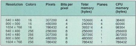
Figure 2: Memory requirements of Super VGA modes
However, Super VGA video modes consume more video memory than is available
in the CPU address space. Figure 2 details typical memory requirements
of Super VGA modes. As is evident from this table, there has to be a mechanism
for the CPU to reach into the video memory using the 64K (or 128K) "window"
available in the CPU address space.
Unfortunately, there are almost as many windowing schemes as there are Super
VGA controllers. Some controllers have one window into the video memory, while
others have two. Some controllers have separate read and write windows, while
others allow read/write in both windows. Some controllers implement a "sliding"
windowing scheme, whereby a window can be placed on any boundary in the video
memory, while others allow placement of the window only on a 64K boundary.
On top of this, the hardware registers that control the windowing scheme are
located at different I/O addresses and require different parameters.
Enter the VESA BIOS Extension
The Super VGA BIOS extension standard, as defined by the Video Electronics
Standards Association (VESA), intends to remedy the incompatibility issues
addressed earlier. The standard tries to address all major problems a software
developer faces when writing software for Super VGA.
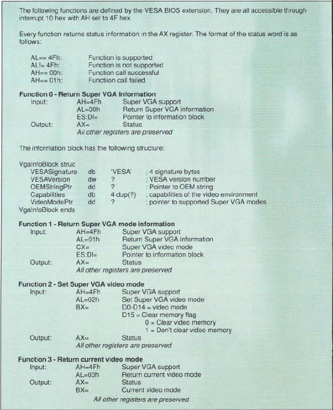
Technically, the VESA BIOS extension is implemented as an addition to the
regular video BIOS, accessed through software interrupt 10 hex. Standard video
BIOS functions are called by placing function numbers in the range from 0 to 1C
hex, depending on the function, in the AH CPU register and then generating a
software interrupt 10 hex. To call a VESA BIOS function, the application would
place the value 4F hex in the AH register, place a function number in the AL
register, and then generate an interrupt 10 hex. Figure 3 describes the
VESA BIOS extension functions.


Figure 3: VESA BIOS extension functions (accessible through interrupt 10 hex with AH set to 4F hex)
The VESA BIOS extension may be placed in ROM together with the regular BIOS.
It may also be implemented as a device driver, loaded by the operating system
at boot time. Initially, most VESA BIOS extensions will be available as TSR
programs. To the application, the method of implementation is irrelevant;
functionally, the BIOS extension behaves the same.
The VESA BIOS extension provides two fundamental services to the application
program:
- Information
- Hardware setup
Global Information
To be able to adapt to a specific Super VGA environment, an application
needs several important pieces of information. First and foremost, an
application needs to know whether the specific environment is indeed capable of
Super VGA resolutions. The application also needs to know whether any VESA
support is available. In addition, certain applications might want to identify
a specific VGA controller.
This kind of global information is provided by VESA BIOS function 0,
Return Super VGA mode information. Before the application calls this
function, it has to allocate a buffer of 256 bytes. The VESA BIOS extension
will fill this buffer with various types of information.
One of the most important pieces of information returned by function 0 is a
pointer to a list of Super VGA modes supported by the display adapter. These
video modes can be VESA-defined modes as well as OEM-defined modes. See
Figure 4 for a list of VESA-defined video modes.
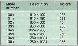
Figure 4: VESA-defined Super VGA modes
Mode-specific Information
To determine the characteristics of a particular video mode, the application
would then call VESA BIOS function 1, Return Super VGA mode information.
Like function 0, the application has to allocate a 256-byte buffer prior to
making the function call.
On return from the function, the VESA BIOS extension will have filled a
Structure, called the ModeInfoBlock, with all relevant information about
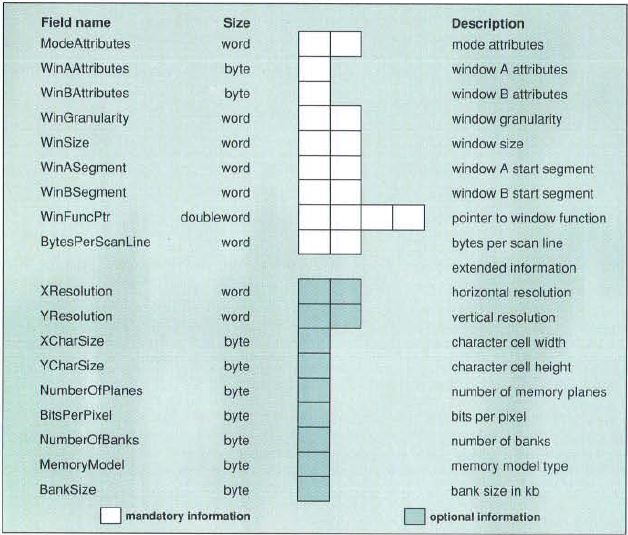
this video mode. See Figure 5 for a description of the
ModeInfoBlock.
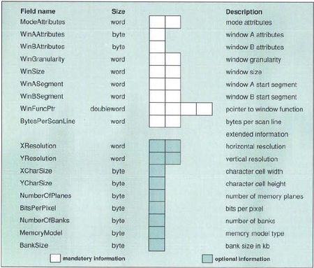
Figure 5: Mode information block structure
Mode Attributes
The first word (16 bits) in the ModeInfoBlock, the
ModeAttributes field, specifies several important characteristics of the
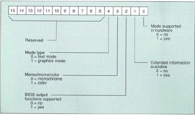
video mode. See Figure 6 for the layout of this field.
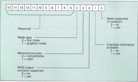
Figure 6: Mode attribute field
Bit D0 in the ModeAttributes field specifies whether the mode is
supported by the present hardware configuration. If a particular video mode
requires a certain monitor, and this monitor is presently not connected to the
system, this bit can be cleared to block access to the mode. Applications
should never try to initialize a video mode whose ModeAttributes D0 is
set to 0.
As will be evident in the discussion later, the VESA BIOS function 0 returns
a lot of information to the application. Some of this information is mandatory,
some is optional. Bit D1 of the ModeAttributes specifies whether any
optional information is available.
Bit D2 indicates whether the output functions (TTY output, set/get pixel,
scroll window, etc.) of the regular video BIOS can be used in this video mode.
It is not mandatory for a VESA BIOS extension to support all or any output
functions in Super VGA modes. The primary reason for this is that high
performance applications handle all output themselves anyway, for performance
reasons. The fact that output support consumes a lot of precious memory space
in a ROM-based implementation was also important in making this support
optional. If bit D2 is cleared, then no output support is available.
Bit D3 specifies whether the mode is monochrome (D3=0) or color
(D3= 1). Bit D4 defines the mode as either text mode (D4=0) or
graphics mode (D4= 1).
Window Description
The characteristics of the windowing system are described in the next field
in the ModeInfoBlock structure. The WinAAttributes and
WinBAttributes identify whether window A and B exist and are readable or
writeable. All Super VGA boards capable of resolutions beyond 640 x 400 in 256
colors and 800 x 600 in 16 colors have at least one window into the video
memory. Applications can determine the existence of a second window by testing
bit D0 of WinBAttributes.
The WinGranularity identifies the smallest address boundary that the
window can be placed upon. In today's Super VGA boards, this varies from 1K to
64K. The WinSize field identifies the size of the windows. In a
single-window system, the size is normally 64K, while in a dual window system,
the size is normally 32K.
The location of the windows within the CPU address space is specified by the
fields WinASegment and WinBSegment. Normally Window A is located
at address A0000. If a second window is present, it would typically be located
at A8000 or B0000. If the VGA controller implements different read and write
windows, the second window could be located at the same CPU address as the
first window. In such a system, a CPU read will access the read window, while a
CPU write will access the write window.
The WinFuncAddr field specifies a direct address to the windowing
function (Figure 3, VESA BIOS function 5). The standard way to access
the video BIOS and the VESA BIOS extension is to generate an int 10.
However, due to the large number of subfunctions using int 10, function
dispatching may take considerable time. This makes int 10 too slow for
some graphics operations. One such time-critical operation is changing the
windowing registers. By using the absolute address to the function, an
application can issue a far call directly into it, speeding up execution
considerably.
Optional Information
Only a portion of the ModeInfoBlock is obligatory information. The other
section is optional and is provided if the specific mode is nonstandard. None
of the modes defined by VESA (see Figure 4) require the optional
information. For an OEM-specific mode, however, the VESA BIOS extension needs
to inform the application about items such as screen resolution, number of
planes, and bits per pixel. Refer to the VESA BIOS extension specification for
information on how to use these optional fields.
Video Mode Initialization
One main objective of the VESA BIOS extension is to help applications set up
video modes. This is realized through VESA BIOS Function 2, Set Super VGA
video mode. The application simply places the video mode to be initialized
in the BX register and calls this function. Normally, the video memory will be
cleared, but if the application sets bit D15 of the BX register prior to
calling the function, the memory will be preserved.
VESA mode numbers are 15 bits wide (see Figure 4). OEM-defined mode
numbers are 7-bits wide and are implemented as a subset of VESA-defined modes.
Due to this numbering convention, VESA modes, OEM-specific modes, and regular
VGA modes can be initialized by using VESA BIOS Function 2.
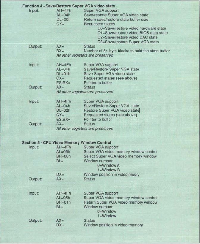
If an application needs to know the present video mode, it would call VESA
BIOS Function 3, Return current video mode. For applications (especially
TSR programs) that need to interrupt other programs, the VESA BIOS Function 4,
Save/Restore Super VGA video state, comes in handy.
The Windowing Function
Finally, the VESA BIOS extension provides a mechanism to control the
position of the video memory windows. This is handled by Function 5, CPU
video memory window control. To reposition a window into the video memory,
the application simply places the window position in the DX register, the
window number (0 for Window A and 1 for Window B) in the BL register, and calls
Function 5.
The window position is not specified as a byte offset, but rather in terms
of granularity units. As stated earlier, the window granularity expresses the
smallest boundary on which the window can be placed. Today's Super VGA boards
have granularities between 4K and 64K. Thus, if the granularity is 16K, and the
application wants to position the window at 64K, the window position is 64/16 =
4 granularity units.
Conclusion
The VESA BIOS extension provides all necessary information and programming
support to Super VGA applications. For the first time, it is possible to
develop generic graphics software, tapping into the exciting capabilities of
Super VGA.
However, just because the VESA BIOS extension has made it possible to write
such applications doesn't mean it will be trivial. Most of the complexity in
dealing with Super VGA stems from managing windows into the video memory.
Anyone already familiar with writing software for one Super VGA board should
have no difficulty in programming others using the VESA BIOS extension.
Bo is a software engineering manager at Chips and Technologies Inc., 3050
Zanker Road, San Jose, CA 95134.
|