|
13W3 to 15-Pin mini-D
HDD15 to 5BNC
13W3 to 5BNC
13W3 Port on GXT150M
Matrox 13W3 to 5BNC Cable
13W3 to 15-Pin mini-D - Detachable Monitor Cable Connectors
(Cable - FRU P/N 96G2156 e.g. used for P70-6544)
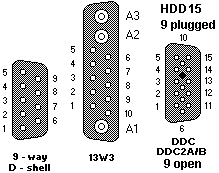
I got the 13W3 pinout from the port of my Image-I. It IS correct.
| Signal Name |
DE9 |
13W3 |
HDD15 |
DDC |
DDC2A/B |
| Video, RED |
1 |
A1 |
1 |
1 |
1 |
| Video, GREEN |
2 |
A2 |
2 |
2 |
2 |
| Video, BLUE |
3 |
A3 |
3 |
3 |
3 |
| Video, return RED |
- |
- |
6 |
6 |
6 |
| Video, return GREEN |
- |
- |
7 |
7 |
7 |
| Video, return BLUE |
- |
- |
8 |
8 |
8 |
| HORIZ SYNC |
- |
5 |
13 |
13 |
13 |
| VERT SYNC |
- |
9 |
14 |
14 |
14 |
| Sync return, Horiz |
- |
10 |
- |
- |
- |
| Sync return, Vert |
- |
4 |
- |
- |
- |
| Sync return, COMMON |
- |
- |
10 |
10 |
10 |
| SELF-TEST |
- |
3 |
5 |
5 |
5 |
| ID-BIT 0 |
- |
6 |
11 |
- |
- |
| ID-BIT 1 |
- |
7 |
12 |
- |
- |
| ID-BIT 2 |
- |
1 |
4 |
- |
- |
| ID-BIT 3 |
- |
2 |
15 |
- |
- |
| DDC - SDA (data) |
- |
- |
- |
12 |
- |
| DDC - SCL (clock) |
- |
- |
- |
15 |
- |
| DDC2A/B POWER |
- |
- |
* |
- |
9 |
| KEY (no pin) |
- |
- |
9 |
* |
- |
Missing Pins
The key position pin-9, above, corresponds
with an obstruction on many system unit video ports, this
is intended to reduce the likelihood of something other than a monitor
being plugged into the port and so offers limited protection to the electronics
on the video adapter card.
DDC uses this pin for power and reassigns the ID bits for DDC signaling.
Older monitors do not use all the pin positions available.
The following were manufactured with pins intentionally missing:
| Machine Type |
Missing pins |
Note |
| 6312 |
9 |
|
| 6314 |
9 - 4,12,15 |
|
| 6319 |
9 - 12,15 |
|
| 6315, 21,22,24,25,27 |
9 |
|
| 6553, 6554, 6555 |
9 |
DDC supported |
| 8503, 8504 (12M) |
9 - 1,3,4,8,11,15 |
|
| 8506 |
9 - 1,3,4,8,11 |
|
| 8507 |
9 - 1,3,8,11,15 |
|
| 8508 |
9 - 1,3,4,8,11,12 |
|
| 8512, 8513 |
9 - 4,12,15 |
|
| 8514 |
9 |
all ID bits supported |
| 8515, 8516, 9515 |
9 - 11,12,15 |
|
| 8518, 9518 |
9 - 4,12,15 |
|
| 9507 |
none |
fully pinned |
| 9521,22,24,25,27 |
9 |
|
Note that 6091I-19i and 9504 use the Image Plus 13W3
connector, which is self-keying by virtue of its three coaxial connectors,
it is always fully pinned.
FRU P/N 96G2688: Standard ID bits, 13W3 - 15-pin I/F cable
(supplied with the RS/6000)
FRU P/N 96G2689: Alternate ID bits, 13W3 - 15-pin I/F cable
Cable / Converter - FRU P/N Reference
| FRU P/N |
Description |
| 40H2934 |
13W3 to 13W3 cable |
52G3282
(52G3255) |
15-pin to 13W3 cable converter |
| 96G2156 |
13W3 to 15-pin cable providing DDC
'Plug and Play' capability. |
| 96G2688 |
13W3 to 15-pin cable providing
'1010' ID bits |
| 96G2689 |
13W3 to 13W3 cable providing
'1010' ID bits |
| 96G2693 |
15-pin to 15-pin cable adapter
providing '1010' ID bits |
| 96G2694 |
15-pin IBM to 15-pin Apple cable
adapter. |
HDD15 to 5BNC
From a cable that Dick Evans gave me, along with a 6091-019, here it is:
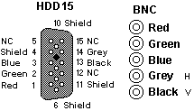
All shields are tied together to shield on HDD15 and pins 4,6,7,8,10,11
Pins 5, 12 and 15 are NC.
13W3 to 5BNC
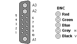
Waiting for SOMEONE to send me the pinout of a WORKING Image-I
to 5BNC cable, used on a 6091-xxx monitor.
13W3 Port on GXT150M
| Position |
Signal Name |
|
A1
|
Red
|
|
A2
|
Green
|
|
A3
|
Blue
|
|
1
|
Monitor ID Bit 2
|
|
2
|
Monitor ID Bit 3
|
|
3
|
(No Connection)
|
|
4
|
I/O GND
|
|
5
|
HSYNC
|
|
6
|
Monitor ID Bit 0
|
|
7
|
Monitor ID Bit 1
|
|
8
|
(No Connection)
|
|
9
|
VSYNC
|
|
10
|
I/O GND
|
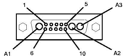
OK, the 150M is PCI, BUT it uses the same cable as the GXT150.
09G3589, FC 4229. It's about 1.83m long.
There is a Display Conversion Cable, 13W3 to 5 BNC, 52G3255 FC4213.
It's about a foot long.
Matrox 13W3 to 5BNC Pinout
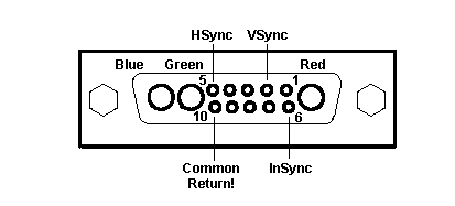
Note: Pin numbering and arrangement
images the GXT150M pinout:
HSYNC uses Pin 5, but the return is Pin 10.
VSYNC uses Pin 2, return on 10.
If you look at the GXT150M pinout:
HSYNC is Pin 5 with return on Pin 4.
VSYNC is Pin 9 with return on Pin 10.
|