|
Source: The Micro Channel Architecture Handbook (page 186-204 physical)
See also: MCA Interrupt Procedures
A major break from the design of classic-bus computers, Micro Channel uses a
level-sensitive interrupt system. Not only more reliable than previous designs,
the new interrupt scheme allows the sharing of interrupts between devices,
giving the Micro Channel a potentially unlimited number of interrupts.
Interrupts and Interaction
Interrupts are what makes your personal computer so personal. Interrupts let
your machine react instantly to the things you demand that it do instead of
single-mindedly churning through one long task or waiting until one job is done
before starting another, Like a fire alarm, when the interrupt clangs for
attention the microprocessor wakes up and does what it has to do, running
through its equivalent of a fire drill. Once the drill is over, the heart
palpitations have ceased, the world has returned to normal near-somnolence, and
the microprocessor goes back to its usual duties.
Unlike fire drills, however, interrupts are the normal course of business
for a microprocessor and they occur somewhat more often — often on the
order of hundreds or thousands per second. And there's not just one drill tor
which to memorize a routine. Microprocessors in PCs must be able to identify
and properly react to more than a dozen distinct hardware interrupts. You've
got it easy when the hallway gong disturbs your daily drudgery.
Interrupts are the key to your computer being interactive. This is,
interrupts allow the machine to respond to events as they happen in real time.
The alternative is for the microprocessor to spin its wheels and wait for the
event to occur. Imagine waiting for a telephone call. You nervously drum your
fingers on the coffee table awaiting the ring, accomplishing nothing in the
interim. You waste time, you get nothing done, except perhaps shortening your
temper.
A microprocessor without interrupts is so simple-minded, it can't do
anything — even chew gum or read a newspaper — while waiting for
the incoming ring. If something should come up in the meantime — should
the microprocessor actually have to think while waiting for the call — it
won't answer the phone until it got the other job done. The phone could ring
for hours.
A microprocessor with interrupts can be doing half a dozen things at once
— calculating square roots, drawing on-screen graphs, buying stocks,
manipulating the junk bond market — and yet still answer the phone on the
first ring. If you're the one making the figurative phone call to the
microprocessor (for instance, by pressing a key at the keyboard), the machine
with interrupt will seem the more responsive. More importantly, the computer
with interrupts will simply get more done in the same length of time.
To understand how important interrupts are, imagine completely losing
control of your computer while it works on a job, so that even when you pressed
keys at the keyboard it would not respond until it had finished with its last
chore. Without interrupts, your computer would have to stop and wait for each
keystroke. It would need to constantly poll the keyboard - stop and take a look
at the electrical signals coming from the keyboard — faster than you
could type. If it missed a keystroke, the letter wouldn't even register.
That's how interrupts make your personal computer more interactive. They
allow the hardware of your machine to signal to its microprocessor that they
have work that needs to be carried out immediately. The interrupt is a signal
that says "Hold everything! Do this first."
All personal computers have the necessary facilities to be interrupt-driven
— that is, the interrupts "drive" the microprocessor by gaining its
attention for the tasks that have the need to be carried out immediately. To
bring this feature to life, these machines need to allow several parts of their
hardware to signal their needs for immediate attention. Typically devices that
need to the instant gratification of an interrupt are things like the keyboard,
floppy and hard disk drives, printers, communications ports, even some
invisible housekeeping functions like keeping up with the time of day or even
system memory. Each of these needs direct access to the microprocessor to
signal their interrupt needs.
From Single to Multiple Interrupts
Just as computers can be built without interrupts, they can be built with
only one interrupt signal, Every system need that required immediate attention
could activate that one interrupt signal and get the attention it wanted. But
when more than one system function demands attention, conflicts can occur as
several different device vie for control of the one interrupt line, Like
jealous children, the competing devices would fight over the microprocessor,
each tugging in it own direction, with no likely resolution. In the end, the
demands of one device might be overpowered by those of another, leaving the
rest unhappy and grumpy. Their dissatisfaction would show in their work —
they would purposely lose data. Moreover, when interrupt demands are in
conflict the computer might not be able to tell which function needs its help.
It might even give one device what another was asking for — and you know
the result of giving a child vanilla when he wants chocolate. The situation is
just as impossible for the computer.
The logical and straightforward thing to do is run out and buy another whole
flock of interrupts. Give each of the greedy children its own interrupt so
there won't be any complaining, Each device that needs it can then have its own
interrupt signal.
Getting enough toys may be difficult, even in this age of affluence. Even
with an excess of playthings, however, something else inevitably ends up in
short supply — Mom. Sated with toys or not, all the kids want her
attention — and they want it now! And although she can distribute the
toys, she can't split her attention.
The equivalent of Mom in most microcomputers — the ultimate arbitrator
— is the microprocessor. Even when (actually, especially when) interrupts
are available in excess, the microprocessor still must divvy up its time to
serve them individually. The big problem is not so much the time required for
servicing the interrupts but sorting through all the conflicting
near-simultaneous demands. When several functions demand attention, the
microprocessor needs some way of telling which is the most important, which
should it work on first — which kid swallowed the Drano and which has
just executed a finger-painting on the new wallpaper in the living room.
Prioritizing Interrupts
To keep order when such conflicting demands arise, IBM Personal Computers do
to the extent of prioritizing interrupts. Each kid gets a number, and Mom wipes
their nose in that order. Each interrupt is assigned an importance, and the
more important take precedence over those of lesser importance. Even the very
earliest of true personal computers, the original IBM PC, prioritized its
interrupt by assigning fully eight levels of priority.
Eight levels of interrupts might seem like a large family —
particularly should you compare it to the five expansion slots offered by the
PC. Every slot could have its own interrupt for whatever purposes might need
it, and three would be left over. Alas, interrupts are so important to the
normal facilities of a personal computer that the use of several interrupts is
required even before the first expansion board is dropped into a slot.
PC Interrupt Assignments
In the PC the division of interrupts seems arbitrary, but its actually well
thought-out. The most important functions always receive the highest priority.
Nevertheless, because the PC was designed as a general-purpose instrument, some
of the choices are not optimal for particular situations. Be that as it may,
certain assignments are given official sanction by IBM, and have become
compatible interfaces for applications.
In all IBM personal computer systems, one interrupt is given over to a
timer. Unless programmed otherwise, this timer generates an interrupt signal
every 55 milliseconds — 15.2 times per second — for use by programs
and other system facilities that need to periodically carry out special
functions. For instance, a program could take advantage of this timer by
jumping into action each time it occurs, checking an important system parameter
(for instance, has the system clock rolled over to a particular hour and
minute? ), acting on the information it has received, then returning the system
to normal operation.
Another interrupt is awarded to the keyboard for its exclusive use. Every
time a key is struck, it generates an interrupt telling the microprocessor to
process the keystroke data coming from the keyboard, This feature allows you to
keep typing while the system microprocessor is involved with other complex
chores, say extensive calculations or simply the act of displaying something on
the keyboard (such as the last key you struck). The interrupt immediately takes
care of your keystroke, then continues on with its other functions.
Normal system options quickly chew through the rest of the original eight
interrupts. The diskette drive requires one so that other system activities
won't ordinarily interfere with reading information from the disk and
transferring it to other parts of the system. In hard disk-equipped systems,
another interrupt is given over to the hard disk drive for the same reason. The
parallel printer port and each of two serial ports also are allowed interrupts
in the standard IBM assignment. As shown in Figure 14.1, in the standard IBM
scheme, only one interrupt is available for more advanced options such as a
network adapter board, micro-to-mainframe communications link, or even a mouse.
Add one of these options, and no interrupts are left for adding any of the
others.
In the PC scheme, installing two devices set to use the same interrupt level
is possible and can work effectively, but the two devices can never be allowed
to operate at the same time. For example, you could install two printer
adapters that use the same interrupt to connect two printers to your system, As
long as you only use one printer at a time, you won't encounter
complications.
If you're on planning using multitasking software, however, that
one-at-a-time restriction may prove limiting — particularly considering
that you (rather than the software) are going to be the one left to manage the
printers. With devices that may unpredictably call for their own interrupts,
the problems are greater. Multiple serial ports, on the other hand, may demand
interrupts simultaneously. For example, you may try to scan a document using
the Windows operating environment using a mouse to select menus. Both the mouse
and the scanner are likely to use interrupts. Were they to share the same
interrupt, conflicting requests could crash your system.
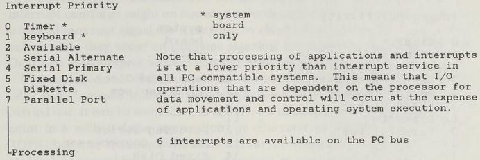
Figure 14.1 PC interrupt priority.
AT Interrupt Assignments
Once PCs moved from hobbyists' workbenches to desktops in offices —
that is, almost immediately — the shortcomings of the limited number of
interrupts became apparent and the future was clear. Personal computers needed
more than eight interrupts, Consequently, the first major revision to personal
computer architecture, the IBM AT, nearly doubled the number of available
interrupts.
This increase was earned by cascading two interrupt controllers together, so
that one group of eight interrupts was routed through one of the inputs of a
second interrupt controller chip. As Figure 14.2 shows, the 15 interrupts of
the AT are just about sufficient for all of the expansion options that might be
connected to a personal computer used by one person.
In a multi-user environment, however, even 15 interrupts may not be enough.
For example, an eight-user system typically assigns each user his own serial
port. What's left is about the same situation as with a single-user PC, but the
expansion options must serve all the needs of seven more people.
Such was the situation when the Micro Channel was being developed. Fifteen
interrupts were teetering on the edge of inadequacy. More powerful computers
— the kind for which the Micro Channel design was destined to serve as a
foundation — would definitely require more. The easy solution was simply
to add more interrupts — a third, fourth, or fifth interrupt controller
and eight to 24 more interrupt request lines on the bus. But if more is better,
even more is better still. And more. And more. The situation would quickly get
out of hand.
The alternative goes back to the original interrupt metaphor — the
harried mom with a dozen nagging kids. Besides giving in to every whim of the
children — an admittedly impossible task — there is another
alternative (although one that can seem difficult if not impossible with kids}:
Teach the children how to share. Once (perhaps, if) you do that, you can cut
down on the number of toys you need to entertain the kids. And you cut down on
the number of personalities the schizophrenic mother must have.
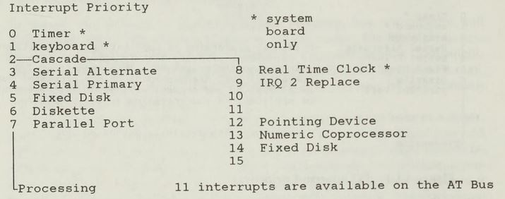
Figure 14.2 AT interrupt priority.
Edge-Triggered Interrupts
Interrupt-sharing in the abstract is a wonderful idea, just as is the idea
of well behaved children. But short of administering psychotropic drugs, the
well behaved child is often a contradiction in terms. Kids just don't act that
way. With edge-triggered interrupts and the PC, the prospects look equally
bleak.
With old-style edge-triggered interrupts, the problem also involves their
inherent make up. By their very nature, the circuits of the PC and AT make
interrupt sharing impossible. This inability results from characteristics of
the signals and circuits of these machines. The hardware interrupt system used
by both PCs and ATs is edge-triggered. Under this arrangement, an interrupt
signal is in effect a portion of a pulse — the interrupt is indicated by
the transition of a voltage from one level to another. Such a transition lasts
only an instant.
That's the problem. Detecting such singular events is fraught with problems.
For example, if you were the lookout on a ship in hostile seas you might miss
hearing a warning shot because you were distracted or not paying attention. Or
two shots might occur so near to simultaneously that you might think it was
only one, Even if you could distinguish the two shots, you might not be able to
individually locate them — you might not be able to cell which one came
from where. Moreover, if you listen with rapt attention to a distant shot that
you expect to be faint, you might misinterpret something else for the shot
— a nearby wave, an engine backfire, or a boatswain's belch, for
instance.
The problems are the same with the interrupt inside a computer system. The
interrupt controller might on occasion miss detecting the sharp pulse of an
edge-triggered interrupt signal. Or it may not be able to distinguish between
two of the pulses when they occur on the same signaling line when an interrupt
is shared. Or it may misinterpret a sharp pulse of noise as an interrupt.
The consequences of these electronic errors may be varied, but they are
inevitably bad. A missed interrupt means that some vital system operation won't
be carried out, [t can be something as trivial as a missed keystroke (say the
decimal point in a million-dollar transaction) or character on the serial port
(like the XOFF character that stops the system from drowning in an unstoppable
stream of data) or something as major as a section of program code that doesn't
get properly loaded from the network interface.
Loss of an interrupt in a multitasking operating system can even require a
reset and restart of the system to re-synchronize the operating system and its
input/output adapters. Noise mistaken for an actual interrupt signal will
likely send the computer on a data processing excursion from which it will
never return. The fake interrupt tells the computer to stop whatever it's
doing, but the impostor doesn't tote along the instructions necessary to tell
the system to go back to work. As a result, the computer's mind may wander
toward the horizon and over the edge of the earth. The system, irretrievably
lost on its way, will hang and be unable to do anything else.
Depending on the circumstance, a confusion of two or more interrupts could
result in either fate — the missed instruction or the errant computer
that never returns to its job. In any case, something bad will have happened,
ranging in severity from errors to system crashes.
Granted the possibility of errors is remote even with edge-triggered
interrupts, but the possibility is finite and measurable, and its likelihood
increases as systems grow in complexity and number of users. Moreover, the
damage done by interrupt errors also increases as the number of tasks and users
grows. Anything that adds to the reliability of the system and the integrity of
its interrupts will help avoid such problems.
Level-Sensitive Interrupts
The Micro Channel lessens the possibility of any sort of these
interrupt-related problem by using level-sensitive interrupts instead of the
edge-triggered variety. Level-sensitive means that instead of being signaled by
the instantaneous transition of an electrical signal, the interrupt is
controlled by a voltage level. That is, a voltage of a designated level stays
present on the interrupt line for the entire duration of the interrupt. By
keying the interrupt to such a continuous level instead of an instantaneous
edge, the problem of missing or misinterpreting the sharp crack of a warning
shot disappears. Instead, the level-sensitive interrupt requires the system's
attention, a warning plume that the computer system can always trace back to
its source.
Level-sensitive interrupts are nothing new or unique. The technology
necessary to create them was available at the time the original PC was
designed, Edge-triggering was simply an expedient design choice for the first
IBM Personal Computers. Remember, IBM never expected that the PC would catch on
as it did. The PC was to be a derivative product of the Data Master/23 office
system for personal use. Indeed, IBM has acknowledged publicly that the company
expected fewer than 100,000 system to be purchased by hobbyists and IBM
employees over a five year period, Developing an entirely new interrupt system
for a computer aimed for a limited market didn't make sense.
Of course, once the choice was made to stick with edge-triggered interrupts,
it had to be maintained throughout the development of derivative computers
(like the XT and AT) for strict compatibility reasons. If it were not,
expansion boards made for the PC would not be compatible with newer systems,
abrogating the principal design tenant of that series of computers —
complete backward hardware compatibility.
Not only was the technology necessary for level-sensitive interrupts
available when the PC was first designed, part of the hardware needed to bring
them to life is present in every PC, a specific integrated circuit designated
by the number 8259A. Simply programming registers in this chip will determine
whether it works with edge-triggered or level-sensitive interrupts. In fact,
the same chip or circuitry that simulates it operation is used in controlling
the interrupt system in IBM's Micro Channel PS/2 models. This is due to massive
requirements set by application software for register compatibility to the
8259A module. The newer systems just program the chip for level-sensitive
operation.
Older computers cannot be converted to level-sensitive operation, however,
because all PC expansion boards expect edge-triggered interrupts. The 8259A
cannot operate in both modes at the same time. If both varieties of interrupt
were occurring in one computer, the interrupt controller could never be sure
what sort of interrupt it would next have to react to.
Outsmarting the Interrupt Controller
The flexibility of the 8259A interrupt controller can also be a problem. The
chip can potentially be programmed to change its operating mode and the type of
interrupts that it uses. Some programs take over the interrupt controller for
their own purposes. And to ensure that all is well when they finish, they
assumed that they operate in a standard PC environment.
Unfortunately the control register inside the 8259A is write-only. It can be
written to and changed, but it cannot be read. That means that a program can't
read the initial state of the interrupt mode, make a change to another mode,
then reset the register to the way it was before the change was made. Even if
it could, a subsequent interrupt service routine might reverse the change.
Consequently, when programs finish using the 8259A for their own purposes, they
reset its registers to edge-triggered operation thinking that they are doing
the right thing to return the system to normal operation.
While this expedient is exactly right for PCs, ATs, and compatibles, it's
exactly wrong for Micro Channel machines. To avoid these difficulties, special
hardware has been designed for Micro Channel computers to prevent their
interrupt controllers from ever being set to edge-triggered operation. The new
circuitry in IBM's Micro Channel computers decodes the same commands as does
the internal logic of the 8259A chip. However, part of the mew circuitry
intercepts commands to reset the system to edge-triggered operation and forces
the interrupt controller to level-sensitive operation in all situations.
Figure 14.3 shows how this system works. When the input/output address for
the control command registers of the interrupt system is decoded by Block A,
the auxiliary edge-triggered command decode logic circuit, Block C, is enabled
at the same time as the 8259 interrupt controller, Block B. The special logic
in Block D passes all commands except the one to set edge-triggered mode to the
interrupt controller, When Block C detects the edge-triggered-mode command,
Block D instead generates a level-sensitive command instead.
The interrupt-mode command is one of several conditions controlled by a
single register within the 82594; therefore only the data bits controlling the
interrupt mode are modified. In practice, Blocks A and B are exactly the same
as they are in ordinary PC/AT implementations, the decoding necessary for Block
C is simple and requires only a few gates. The interrupt-mode-control command
has two states — it's only one bit in a single register — so it
requires only a single exclusive-or gate to invert the state of the bit during
the set edge-triggered mode command, In effect, this design exchanged potential
(and unnecessary) flexibility for reliability and the assurance of proper
operation of the interrupt system.
Logic Families
When interrupts are shared between several devices, level-sensitive
technology complicates the circuit designer's job slightly. The designer must
use only the recommended type of interrupt request driver and, as explained
later, must add a single register that is readable at an 10 address for each
adapter.
Typically computer circuits are built using bipolar logic chips. That is,
the logic elements in the integrated circuits have two states (the two poles of
the bipolar name), the logical true or false, one or zero, on or off.
Electrically, the circuit either produces an output voltage of a certain level
(nominally five volts) to indicate a logical one or near zero volts to indicate
a logical zero. When the outputs of two circuits are coupled together, as they
would be in an interrupt sharing system where multiple devices use the same
interrupt line for signaling, the connected circuits could fight one another
when one calls for an interrupt and another does not. The one that wants to
signal an interrupt would do its best to raise its output to five volts while
the other signal would work as hard as it could to lower its output to zero,
All the power from the first circuit would go directly to the second with the
result being a short circuit. One or the other circuit would fail from
attempting to produce or eliminate (in technical terms, source or sink) too
much current.
Conventional edge-triggered cards in PC/XT/AT designed computers use these
bipolar driver circuits. Normally, they are not designed to share interrupts.
Even if they did, the quick pulse that produces the voltage edge needed to
signal the interrupt would not unduly stress the circuitry. It would likely be
too brief to do damage. Run the same circuitry in level-sensitive mode or
repeatedly overlap the pulses, and the first shared interrupt could result in a
circuit failure.

Figure 14.3 Edge to Level Interrupt Command Modification.
The Micro Channel design avoids such devastation by driving the common
interrupt request lines on the bus with circuits that use a special technology
called open-collector drivers or with tri-state drivers operating as
open-collector circuits. The distinguishing design element of open-collector
circuits is that they can only drive the zero logic state. The one logic state
is established by current supplied from the system through a resistor, Current
to restore the voltage is always available through the resistor. When the
open-collector circuit outputs of logical zero, it effectively shorts out the
voltage provided by the through resistor, and the resistor limits the current
flowing through the open-collector circuit to a level well below that which
could cause damage, This circuit design allows multiple outputs to be safely
connected together because they don't fight one another. The open-collector
chips with zero outputs simply ignore the voltage produced by a one output.
Figure 14.4 Mixing of 2 bipolar
drivers for edge triggered interrupts can produce a
momentary short-circuit if two adapters try to drive the
line in opposite directions.
Under the Micro Channel specification, each expansion board must incorporate
an interrupt-pending status register that can be read by the software running
on the system at an input/output address. By polling this register, a program
can determine which of several expansion boards sharing the same interrupt
request line are activating that interrupt.
The Micro Channel specifications require that once an expansion board sets
an interrupt request on the bus, it must hold that request line active until
reset by the interrupt service routine, The software that determines which
expansion board initiated a specific interrupt request will typically provide
that interrupt service routine. The interrupt request may be reset implicitly
as a command that's part of the control operation of the program or explicitly
through a specific port defined for resetting the interrupt.
The interrupt-pending register is set when the interrupt request is
activated on the bus. It is reset before or at the same time as the interrupt
request. Some adapters may merge the two registers into one for simplicity. See
Figure 14.5.
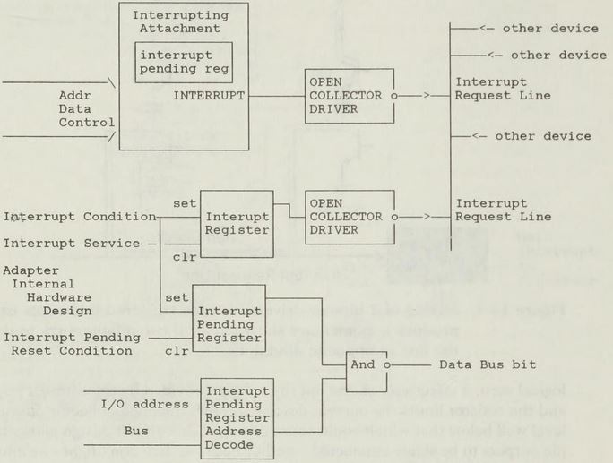
Figure 14.5 Each adapter contains
an interrupt-pending register.
Because of the physical differences between the Micro Channel cards and
expansion boards designed for the PC bus, hardware compatibility between the
two types of boards was unnecessary. Consequently, the Micro Channel
specification requires that all interrupt lines be driven with open-collector
drivers or tri-state drivers wired as open collector, This design eliminates
any likelihood of circuit damage when sharing interrupts. One need not worry
about a newly installed circuit card with a bipolar output might effectively
sabotage a system that was otherwise equipped with open-collector logic. Only
by breaking with the past was the Micro Channel standard able to use
level-sensitive interrupts safely with the potential for interrupt sharing.
How an Interrupt Works
Despite their power, interrupts are actually simple operations. The only
complication is the required interaction between hardware and software.
An interrupt begins when a critical event happens to any device attached to
a computer's circuitry. If that device is interrupt driven, through its own
components it will generate an interrupt signal that is sent to the computer's
interrupt controller down one of the dedicated interrupt lines of the expansion
bus.
Upon receiving the signal on the interrupt line, the interrupt controller
immediately signals the microprocessor across a special input line, Through the
interrupt controller, the microprocessor checks which interrupt line was used
for the original signal. Once the interrupt line is identified, the interrupt
controller indicates the appropriate information, called an interrupt vector
for the active request, The interrupt controller determines the priority of
interrupt-pending requests, and presents the interrupt vector associated with
the interrupt with the higher priority to the microprocessor.
The interrupt vector is simply a particular place in the microprocessors
memory that holds the microprocessor's address of the first of the instructions
that the microprocessor is supposed to carry out to execute the interrupt. Once
the microprocessor find the vector to use, it starts executing the program code
at the address the vector points to.
At this point in a conventional edge-triggered system, the software is in
total control. The pulse of the edge-trigger itself has passed and is of no
more concern to the system, The interrupt software now instructs the
microprocessor exactly what to do. For example, a keyboard interrupt tells the
microprocessor to read the register where the keyboard hold its latest
keystroke, move the keystroke data into memory, then signal to another register
that tells the keyboard that the character has been read. At the end of the
interrupt instructions, it is the software's job to mop up the mess that it
made. [t must reset the interrupt controller by issuing an End of Interrupt
(abbreviated EOI) command to it, then tell the microprocessor to go back to the
point at which it left off to jump to the interrupt vector.
It is important to note that edge-triggered interrupt service routines will
typically issue the EOI command early in the routine to re-enable the interrupt
controller so that it can resume checking for interrupts. Level-sensitive
interrupt service routines must delay their EOI commands until after the
interrupt request has reset the expansion board requesting the interrupt.
Consequently another problem of systems that support both edge- and
level-sensitive modes is selection of the proper interrupt service routine
(usually contained in the device driver).
The interrupt controller is charged with the responsibility of keeping
multiple (and simultaneous) interrupts straight. It may allow an interrupt with
higher priority to break into an executing interrupt of lower priority. Or it
may stack up interrupts, including those that may occur simultaneously, to
execute them sequentially in order of importance.
Micro Channel Interrupt Operation
Micro Channel systems tie interrupt hardware and software more closely
together by specifying a much more rigorous command structure. Every detail of
interrupt operation is laid out by the Micro Channel specification.
The interrupt begins in the same manner as the interrupt on earlier personal
computers. The occurrence of a critical event in an interrupt-driven causes the
adapter device to send a signal down a particular interrupt line. In the Micro
Channel scheme, however, the same condition also causes the device to set the
interrupt pending latch. The state of this latch can be read by the interrupt
software to determine which of many devices potentially connected to the same
interrupt line actually requested the interrupt.
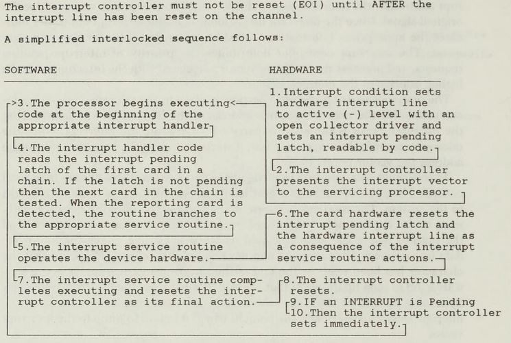
Figure 14.6 Level-sensitive
interrupt sequence with sharing.
Upon detecting the voltage level indicating an interrupt on any interrupt
line, the interrupt controller signals to the computer's microprocessor that it
should begin servicing the interrupt. As before, the interrupt line used for
signaling the interrupt controller tells the microprocessor which interrupt
vector to use. The microprocessor stops executing the program it was executing
in before the interrupt occurred and instead starts executing the code at the
address to which the interrupt vector pointed. However, the voltage indicating
the interrupt remains present on the designated interrupt line.
As one of its first operations, this interrupt software reads the
interrupt-pending Latches of all devices connected to the interrupt line that
was activated. Typically, the software will check each of these expansion cards
one by one until it finds one that has its interrupt-pending latch set. This
system allows the program to branch or execute different streams of
instructions depending on the device that activated the shared interrupt. Each
device that uses a given interrupt line may have its own separate
interrupt-handling routine. Just as the number of the interrupt line indicated
which interrupt vector for the microprocessor to use, the activated
interrupt-pending latch indicates which program branch to take.
Finally, the interrupt has reached the point that its specific task can be
carried out. Again, it can be something as simple as reading a keystroke or as
complex as transferring a block of data from a hard disk.
Once the necessary actions are taken in servicing the interrupt — for
example, loading the register that indicates a keystroke has been properly read
— the hardware device that sent the initial interrupt signal removes the
voltage level from the interrupt line. At the same time, the interrupt-pending
latch of that device is also reset.
After the interrupt signal ends, the interrupt software cleans up alter
itself. Its final action is to send an End of Interrupt signal to the interrupt
controller. This signal resets the interrupt controller and makes it ready for
the next interrupt. If another interrupt has occurred, then the controller
immediately starts the entire process afresh, It will continue to step through
each pending interrupt until all have been serviced.
If multiple interrupt-pending registers are simultaneously active, the
software designer has two choices. The first choice is to resolve each
interrupt in turn as it is discovered, Alternately, the designer can build a
table of all pending interrupts and prioritize the list as to sequence of
service. While the second choice may be optimal for some configurations, the
first choice is the easiest to integrate with existing PC systems.
When the PC interrupt service routines for DOS are each loaded into the
system, they are assembled into a sequence. The first routine to be installed
is pointed to by the interrupt vector. This first routine indicates the point
of return where normal program execution will return on completion of the
interrupt. With only one routine and one device (no sharing) the
interrupt-pending register should always be active, and the routine will
execute whatever the expansion board requires, then return to the point in
program execution where the interrupt occurred.
For example, with DOS, if more than one interrupt service routine is defined
for a level (that is, if the interrupt is shared), then the second routine
places its start address as the vector pointer and uses the original vector
contents as its return or exit pointer. That is, upon completion of the first
interrupt, control is handed over to the routine pointed to by the second
interrupt vector, Multiple interrupt routines can be linked together
sequentially in this fashion, the last one added becoming the first one to be
executed. See Figure 14.7. That is, the sequence is the reverse order of
installation. This loading and linking of interrupt vectors for the various
interrupt service routine is generally performed by the system's Power On Self
Test procedure.
Note that if two interrupts that share the same interrupt line occur
simultaneously or nearly so, the software will have to sort them out. The first
time execution runs through the interrupt software, it causes execution to
branch to the part of the program designed to service the hardware on which an
active interrupt-pending latch was detected first. The second time it runs
through the code that's located at the interrupt vector, this first
interrupt-pending latch will have been reset (and thus ignored). The program
will then detect the second activated interrupt-pending latch and execute the
program branch dedicated to it.
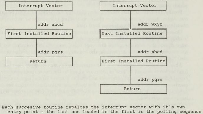
Figure 14.7 DOS example Interrupt
sharing polling sequence.
Interrupt Overhead
When interrupts are shared, additional software and hardware overhead is
imposed on the system. The interrupt-handling software is forced to step
through and evaluate the condition of each interrupt-pending latch connected to
a given interrupt line. Because of all the program branches, the
interrupt-handling program also becomes larger, perhaps prodigious.
Consequently, the first casualty in sharing interrupt can be performance. Stack
a dozen devices on a single interrupt line, and the time required to service
interrupt may become prohibitive. Thus, although the POST architecture imposes
a limit of 255 interrupt service routines per system, practical matters of
performance restrict how many devices may he desirable. A common service
routine to a family of devices, all co-resident in the same system, could
create a list of adapters with pending interrupts for efficiency.
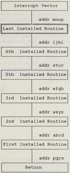
Figure 14.5 DOS example: Long Interrupt sharing polling
chains are possible.
Additionally, the portion of a microprocessor's time that devoted to
servicing shared interrupts depends on how powerful the chip is. What may take
most of the time of a slow, primitive microprocessor like the 8088 could be
handled with but a fraction of the power available in an 80386DX or 80486. As
systems become increasingly powerful, their ability to handle shared interrupts
will increase accordingly.
But as systems are put to work on running more complex programs, the
fraction of the system's time devoted to servicing interrupts can increase
dramatically. In multi-user and multitasking systems the burden of processing
interrupts can become heavy. Thankfully, optimizing interrupt operation is not
difficult with Micro Channel Architecture, as the next chapter show. Moreover,
other Micro Channel facilities, such as Subsystem Control Block Architecture,
help to control complex systems with a minimum of interrupt overhead.
Summary
Only by totally breaking with the past and foregoing compatibility with PC
and AT expansion boards were the Micro Channel architecture designers able to
develop its new level-sensitive interrupt system. Level-sensitive interrupts
are inherently more reliable than the edge-triggered kind used in earlier
personal computers. They are less prone to confusing noise with actual
interrupts and help avoid losing interrupts when they occur nearly
simultaneously.
Level-sensing also makes possible interrupt sharing and allows a single
interrupt to be shared among a number of expansion devices. Instead of being
restricted to the actual number of interrupt request lines, shared interrupt
are essentially unlimited in number. And that's the strong suit of
interrupt-sharing in the long run. The technology offers growth in system
services that's commensurate with the increase in system power. Interrupt
sharing is the choice for the future in personal computers.
| 