|
Sources:
SA23-2647-00 RS/6000 Hardware Technical Reference - Micro Channel Architecture, 1st Ed., 1990
The Micro Channel Architecture Handbook (Chet Heath, PBUH!)
You need to borrow it from the Internet
Archive. Unfortunately, it is locked up tighter than a drum,
so it is easier doing screen caps then recognizing it...
YMMV, LFO
US5187781 Shared hardware interrupt circuit for personal computers
Interrupt Procedures
This section describes how all devices use interrupts. The
procedure for sharing interrupts uses a request for
interrupt services that is detected by the level of the
interrupt request signal (level sensitive). These procedures
involve the interaction between the hardware and an
interrupt service routine.
To initiate an interrupt request, a device drives its
-IRQ(N) active (N represents the assigned interrupt level
for the device) and holds the signal active until it is
reset by the interrupt service routine.
Each device provides an interrupt-pending bit within its
address space. This bit is set by the device when it has an
interrupt request pending and is reset by the interrupt
handler when the interrupt request is serviced.
Note: The drivers for
the interrupt signal must be disabled when the device is
disabled.
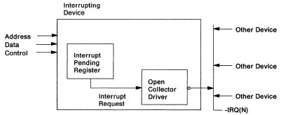
Figure 1-60. Typical Adapter Interrupt Sharing Implementation
An example of the sequence of the hardware and interrupt
service routine interaction is shown in the following.
Hardware Operation
An interrupt condition causes the hardware to drive
-IRQ(N) active and sets an interrupt-pending latch, which
can be read by software. Software Operation
A master begins executing code at the beginning of the
appropriate chain of interrupt handlers. The interrupt handler reads the interrupt-pending latch
of the first device in the chain. If the latch is not set,
the next device in the chain is tested. When the reporting
device is detected, the handler executes the service
routine. The interrupt service routine operates the device hardware. Hardware Operation
The device hardware resets the interrupt-pending latch
and the interrupt request because of
interrupt-service-routine actions. Software Operation
The interrupt service routine completes the interrupt
processing. Hardware Operation
If another interrupt is pending (-IRQ(N) driven active by
another device), the sequence starts again at 1.
Edge Triggered Interrupts
"The PC AT uses an edge-triggered interrupt request
signal. That is, where an adapter requests an interrupt so
that its device may be serviced, it does so, e.g, by first
driving the interrupt request line to a low level and then
to a high level. The transition between the low level and
the high level is received by the system as an interrupt
request signal.
Where the computer is being used for multi-tasking and or by
multi-users, it may be desirable to add more devices than
there are hardware interrupt levels. This can create system
problems. For example, if two tasks were to "talk" to the
same printer at the same instant and time, the result would
be incomprehensible. Still another task might require a
special printer or plotter for output. Most
interrupt-supporting adapters were designed to first drive
the interrupt request line to a low level and then to a high
level to provide a low-to-high edge signal which is
interpreted, under control of software drivers, by the
microprocessor and by the interrupt controllers as a request
for servicing, i.e. a hardware interrupt request signal.
A problem arose where two such devices were connected to the
same level interrupt and the devices requested interrupts at
the same time or where one interrupt was being handled when
a second request was generated. The occurrence of these
conditions could cause lost signals and even physical damage
to the I/O device adapter.
The PC AT could be used to provide sharing of an interrupt
level between multiple devices, however, this required a
change in design of many device adapters which were to share
an interrupt request level and created compatibility
problems with earlier designed cards. Adapter cards
previously designed for non-interrupt level sharing were
designed to hold the interrupt request line at a low level
and then to drive the line high to generate a request
signal.
In contrast the shared-interrupt card design, to operate in
the PC AT, the PC XT or the PC called for the interrupt
request line to float high, through pull-up resistors on
each adapter and typically to be driven by open-collector
drivers. Each adapter on the line may request an interrupt
by momentarily pulsing the line to a low level. The
high-to-low transition arms the Interrupt Controller; the
low-to-high transition generates the interrupt. It was
accordingly not possible in most cases to use the adapters
not designed for shared interrupt use in a shared
environment. It has been found that the use of more than one
adapter card on an interrupt request level, whether
specifically designed for interrupt sharing or not, may
cause physical damage or loss of signal where more than one
of the adapters is active at the same time."
FIG. 1
"Referring now to the drawings there is shown in FIG. 1 two
device adapter cards shown generally as 1a and 1b. Included
on adapter 1a, 1b are edge-triggered interrupt request
circuits shown generally as 3a and 3b. As described above
the interrupt request signal is a momentary pulse generated
by the interrupt request circuit, 3a, 3b. The interrupt
request line 5 is first pulsed low to arm the Interrupt
Controller 22, (see FIG. 3B), and then pulsed high to
request the interrupt. The transition from low to high
generated by circuits 3a and 3b and transmitted to the
interrupt request line 5 is received by the microprocessor
and interrupt controllers as a request for attention by an
I/O adapter 1a, 1b. To create this transition of the
interrupt request line 5 from low to high line 5 must first
be driven low and then driven high. Circuits 3a and 3b
provide this transition. Circuits 3a, 3b in this exemplary
instance includes power supply lines 7a, 7b and ground lines
9a, 9b which are connected to a common source of power and
ground on the system planar when the adapter cards are
plugged into the I/O connectors or slots 22 (see FIG. 3C).
Each circuit 3a, 3b incorporate a low transistor 11a, 11b; a
high transistor, 13a, 13b, and a diode 15a, 15b. An
interrupt request signal is generated as follows: The low
transistor, 11a, 11b is turned on to drive the interrupt
request line 5 to a low level by connecting it, through
adapter interrupt request output line 17a, 17b to ground 9a,
9b. The signal is then generated by turning the low
transistor 11a, 11b off and high transistor 13a, 13b on.
This sequence provides the low to high transition, i.e. a
rising edge signal, that tells the system that a device
adapter is requesting attention through a hardware interrupt
request.
Short Circuit Interrupt on PC vs. MCA Bus
"Conventional edge-triggered cards in PC/XT/AT designed
computers use these bipolar driver circuits. Normally, they
are not designed to share interrupts. Even if they did, the
quick pulse that produces the voltage edge needed to signal
the interrupt would not unduly stress the circuitry. It
would likely be too brief to do damage. Run the same
circuity in level-sensitive mode or repeatedly overlap the
pulses, and the first shared interrupt could result in a
circuit failure". Micro Channel Architecture Handbook, page
96.
So, IBM was faced with a problem if they used the older
bipolar "Totem Pole" circuit. "When the outputs of two
bipolar chips are connected together, they fight one
another. When one chip is on and the other is off, the
result is effectively a short circuit. The "on" chip pushes
out all the current it can to try and force the "off" output
into an "on" condition - something it cannot do. The "on"
chip may pump more current than it is designed to, and the
"off" chip is forced to absorb all the current to remain
off. With time, the resulting overload can damage either or
both chips." Micro Channel Architecture Handbook, pages
85-86.
Note: This illustration
from "The Micro Channel Architecture Handbook" uses
conventional current flow, as evidenced by the arrow head
pointing down into ground. Actual electron flow is up from
ground to the more positive end. Think of your car battery.
Negative ground. Except the old stuff, or European cars...
Also note that the emitter arrow head on the transistors
points to the negative side (electrons flow into the arrow
point).
"The problem with using this design in a shared interrupt
environment can now be understood. As an example, assume
that adapter la has driven interrupt request line 5 to a low
level by connecting interrupt request line 5 to ground 9a
through active transistor 11a at the same time that adapter
1b high transistor 13b is active. This would result in
momentarily grounding the system power supply source through
power supply line 7b, transistor 13b, diode 15b, and
transistor 11a. This destructive passage of current could
result not only in loss of the interrupt request signal from
adapter 1b, but in damage to the physical components such as
the transistors. Resistors could be placed between the
adapter cards and the interrupt request line to limit the
current, however, this solution would decrease the "noise"
margin for the logic and aggravate noise problems in the
system. These problems can be overcome by the system of the
present invention."
Level Sensitive Interrupts
"The present invention allows multiple adapters to be
used on a single interrupt level without loss of an
interrupt request signal or physical failure of a system
element. The present invention utilizes diodes positioned
between each adapter and the interrupt request line.
Further, a pull-down resistor and a Schmitt trigger are
incorporated in the interrupt request line in the preferred
embodiment. The diodes prevent the short-circuiting of the
adapters when two or more active adapters are in electrical
contact with the hardware interrupt request line at the same
time. The pull-down resistor and Schmitt trigger are used to
convert the diode-modified interrupt signal to a signal
which can be utilized by the microprocessor and interrupt
controller system under control of software device drivers."
FIG. 2
Referring now to FIG. 2, there is shown a modification to
the circuitry shown in FIG. 1 in accordance with the present
invention. The advantages of this invention may be obtained
by incorporating diodes 19a, 19b between the adapter
interrupt request output lines 17a, 17b and the interrupt
request control line 5. Diodes 19a, 19b prohibit the passage
of current from one adapter e.g. 1a to a second adapter 1b.
It is well known that diodes can be designed to prohibit the
passage of electrical current in one direction only, and to
limit the amount of current passing. The preferred diode for
the present concept would be a diode that had a minimal
forward voltage drop characteristic. The introduction of
these diodes requires other modifications to the system to
allow adapter cards 1a, 1b to remain compatible with
existing systems. A pull-down resistor and ground shown
generally, as 23 are used to keep the interrupt request line
5 at a low level. A Schmitt trigger 21 is provided to detect
a slow transition of the signal placed on interrupt request
line 5 by adapter card circuit 3a, 3b. The output of the
Schmitt Trigger 21 is connected to the input of an Interrupt
Controller 20 (see FIG. 3B). This combination of components
provide in response to the low-to-high signal generated by
the adapters 1a, 1b over adapter output lines 17a, 17b a
signal on the interrupt request line 6, that transitions
from low to high and is suitable as an edge-trigger
interrupt request signal.
In operation, if any of the drivers, circuits 3a and 3b are
active high, the interrupt request line 5 will be high. If
all drivers are low, or if all drivers are not active, the
interrupt request line 5 will be low. The Schmitt trigger
inverter 21 inverts this signal to provide a low signal to
the processor 29 (see FIG. 3A) and interrupt request
controllers 20 over interrupt request bus 6 (see FIG. 3 for
a typical planar bus system layout). The following Table
demonstrates the possible combination of operations
| Adapter Output |
Interrupt Request Signal |
| 1a |
1b |
Original |
Inverted |
| 0 |
0 |
0 |
1 |
| 0 |
1 |
1 |
0 |
| 1 |
0 |
1 |
0 |
| 1 |
1 |
1 |
0 |
The original signal is the logical "OR" of all active high
requests usable for low-to-high edge detection processes. An
inverted signal is the low active level request potentially
useable for low level-sensitive, as contrasted to
edge-triggered, detection for certain adapter combinations.
No invalid levels are produced and no potential overheating
of the adapter circuits will result. The inverted output
combination is similar to that produced by open collector
drivers in a level sensitive interrupt system such as is
used in the Family II models of personal computers listed
above.
It should be pointed out that custom software drivers are
required to be installed in the operating system of Family I
computers for adapters 1a, 1b to be able to share interrupt
levels in accordance with the present concept. Further, only
adapters that can respond to these drivers and hold the
interrupt request active until the activating adapter can be
selected from the other possible adapters could be used.
These drivers are written to hold the interrupt request low
except when the interrupt is requested. On existing
adapters, where an active edge-triggered interrupt request
is not held low by the hardware, or where software drivers
cannot hold the interrupt request line 5 low, these adapters
could not share an interrupt level. Many adapters however
meet these requirements for sharing, other adapters could be
designed to work in non shared edge-triggered systems and
also work in the present system.
The present concept provides a level sensitive system that
can be operated in a manner similar to the level sensitive
system exemplified by the Family II computers. The Schmitt
trigger provides a level sensitive, as contrasted to
edge-triggered, signal to the processor 24 and interrupt
controllers 22."
|