|
r700m120.exe ThinkPad 700 Reference Disk (v1.20) (zipped image)
r700c120.exe ThinkPad 700C Reference Disk (v1.20) (zipped image)
dg720120.exe ThinkPad 700, 700C, 720, 720C Diagnostic Disk (v1.2) (zipped image)
700c120.exe ThinkPad 700C, 720C Video Driver 256 Color (v1.20) for Win3.1
700propm.exe ThinkPad 700C, 720C Video Display Control for OS/2
700 Planar Top
700 Planar Bottom
System Firmware
ROM Images
CPU Board
Video Card
Keyboard Control Board
Voltage Convertor
Most photos and provided by Eric Schlaepfer aka "Tube Time".
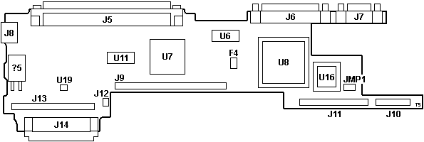
ThinkPad 700 Planar Top FRU P/N 49G1975, SUB P/N 49G1973, P/N 39G9967
![Top [P]](/other/img/photo.gif)

F4 SMD fuse 1 A / 125 V
J5 240-pin System-Expansion connector
J6 Parallel port
J7 DE9 Serial port
J8 External Input Device connector
J9 Video Card interface
J10 Diskette Drive Connector
J11 Base Memory Card interface
J12 Backup Battery connector
|
J13 Processor Card interface
J14 Hard Disk Drive connector
JMP1 Password-override header
U6 LT1137CS RS232 Transciever
U7 82077SL Floppy controller
U8 39G9988
U11 Dallas DS1485S RTC/CMOS/NVRAM
U16 ROM BIOS 39G9996
U19 LM386 Audio op-amp (PC Speaker)?
|
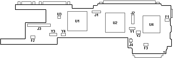
ThinkPad 700 Planar Bottom
![Bottom [P]](/other/img/photo.gif)

F1-3 SMD fuse 2 A / 125 V
J1 System Status Indicator connector
J2 Keyboard Control Card interface
J3 Voltage Converter interface
J4 Speaker connector
U1 48G8903 (old) or 48G8905 (new)
U2 89F6841 mwave
|
U3 OKI MSM16811P "M811P" 1Kbit EEPROM
U4 95F3690
Y1 32.768 kHz xtal
Y2 14.318 MHz osc
Y3 10.000 MHz osc
Y4 24.000 MHz osc
|
System Firmware (POST & BIOS)
Simplified firmware stored in EPROM. IML image required for the system to operate.
(Why is it 256 KB then?)
ROM Images
39G9996 - 03 Sep 1992, rev. 42h, 1x 27C201 PLCC32 (U16)
CPU Board P/N 39G9762
![Top [P]](/other/img/photo.gif)
![Bottom [P]](/other/img/photo.gif)
The ThinkPad 720 and 720C systems have a IBM 486SLC2 50/25MHz microprocessor
and a math coprocessor socket for an optional Intel 80387SL processor.
Y1 40.000 MHz osc
Y2 50.000 MHz osc
U1 33G0396 486SLC2
U2 PLCC-68 math co-pro socket
Video Card FRU P/N 35G4781, P/N 39G9795
![Top [P]](/other/img/photo.gif)

|
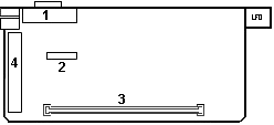
1 External Display Connector
2 LCD Connector
3 System Board Connector
4 Communication Adapter Connector
|
ICS2494M Dual Video/Memory Clock Generator
2x Toshiba TC511665BJL-80 64Kx16 DRAM
Video Card Bottom
![Bottom [P]](/other/img/photo.gif) | |
![Bottom (alt) [P]](/other/img/photo.gif)
39G8600 SVGA controller
2x Toshiba TC511665BJL-80 64Kx16 DRAM
Keyboard Control Board FRU P/N 54G0468, P/N 39G9986
![Top [P]](/other/img/photo.gif)
![Bottom [P]](/other/img/photo.gif)

1 Pointing Stick connector
2 System Board interface
|
3 Keyboard connector
4 Keyboard connector
|
Voltage Convertor FRU P/N 48G3712, P/N 35G4785
![Top [P]](/other/img/photo.gif)
![Bottom [P]](/other/img/photo.gif)
Eric Schlaepfer aka "Tube Time" reverse engineered the power board!
Schematic: GitHub repository,
local PDF

1 Power Jack
2 Battery Pack interface
3 System Board interface
|
4 Standby Battery connector
5 Suspend/Resume switch
|
Test 700 Voltage Convertor
Test 720 Voltage Convertor
|