|
AC Adapter
Lind Electronics DC Power Adapter
NiMH Battery Pack
NiMH Battery Pack with Power Status Indicators
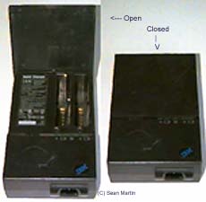
Quick Charger
Power Systems Checkout
AC Adapter
Car Battery Adapter (700 only)
Battery Pack
Backup Battery
Standby Battery
Quick Charger
Voltage Converter (700, 700C)
Voltage Converter (720, 720C)
AC Adapter
The AC adapter is an AC to DC converter which supplies
the necessary power to the computer. The AC adapter also charges the battery
pack when it is installed in the computer.
Input rating: 100-240 V AC, 2.0A, 50/60Hz
Output rating:
+20 V DC 2.0 A
+20 V DC 2.5 A (Expansion Cartridge attachment)
Operating temperature 5 - 35 °C (41 - 95 °F).
Lind Electronics DC Power Adapter
(Model
# IB2020-154 )
Automotive DC adapter.$89.95 list.
Housed in indestructible extruded aluminum cases & sealed for durability!
All Lind adapters have built in noise & spike protection!
Use in Car, RV, Boat or any 12VDC source!
3 year warranty includes repair of damaged or broken plugs or cables!
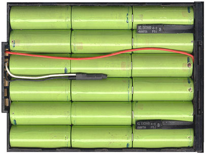
NiMH Battery Pack
Battery Pack: 10.8 V DC, 1450 mAh/cell, 18 cell/pack
Rechargeable battery pack for 4 to 8 hours (monochrome) or 2.4 to 4.8 hours
(color) of use, depending on operating, environmental and application
characteristics. When on AC power, an idle or operating system unit can charge
the battery in approximately 1.5 hours (monochrome/color). The system internal
quick charge takes approximately 1.4 hours (monochrome/color) during Suspend
and power-off with AC adapter connected.
The battery pack is an internal power source to the computer when the AC
adapter is not available. The battery pack is rechargeable and is charged using
the AC adapter or the ThinkPad Quick Charger, which can charge two battery
packs simultaneously.
With a fully charged battery pack, the user can operate the computer up to 8
hours (monochrome) or 4.8 hours (color) depending on the application and the
configuration usage. PC Cards that do not support the power management function
may cause the shorter battery operation hours.
In summary, the battery operation hours and charging hours are:
| Function | Monochrome | Color |
|---|
| Power off/Suspend charging | 1.4 hours | 1.4 hours |
| Charging during operation | 1.5 hours | 1.5 hours |
| Quick charging | 1.4 hours | 1.4 hours |
| Suspend Life (Full) (*) | 48 hours | 36 hours |
| Suspend Life (Partial) (*) | 6.0 hours | 6.0 hours |
| Battery Operation Hours (**) | 4.0 - 8.0 hours | 2.4 - 4.8 hours |
Notes:
(*) Full battery.
(**) Power management and application dependent.
PC Cards that do not support the power management function may cause the
shorter battery operation hours.
The ThinkPad 700 and 720C systems also support a suspend/resume function
when the PCMCIA card is installed. For example, when you are operating with the
communication application with PCMCIA cards, after suspend/resume you do not
need to restart the operating system and communication application.
|
The two fusible links are Klixon 4-S F5J 4MM75A
The central item is a PTC resistor (I think)
|
NiMH Battery Pack with Power Status Indicators
This has five power status LED indicators and one push button located on the
front bezel of a battery pack. These LEDs show how much battery power remains
when the button is pushed. In full-charged state, all five LEDs are lit. One
LED means about 20% of battery power. The battery operation hours and charging
times are the same as the standard NiMH battery pack.
Quick Charger
The quick charger has two slots to charge two battery packs simultaneously.
Charging begins on the first battery pack installed, then after it is
completely charged, the other installed battery pack is charged. A REFRESH
BUTTON is provided for each battery pack slot to DISCHARGE the battery packs
before charging them. There are identifiers and indicators that tell the
charging status for each battery pack installed.
Power Systems Checkout
Note: One or all of the batteries
can discharge if there is a short circuit in the system.
1. Replace the failing FRU if the power supply problem is caused by
a short circuit.
2. Determine if one (or all) of the batteries have become discharged.
Replace any discharged battery with its spare, if available.
Checking the AC Adapter (25W or 40W)
If the Power-On indicator does not turn-on, check the
power cord of the AC adapter for correct continuity and installation.
1. If any noise can be heard from AC adapter when it is plugged into
ac power outlet, replace AC adapter. If no noise can be heard from AC adapter,
go to step 3.
2. If a noise is still heard from new AC adapter, suspect the computer.
Replace AC adapter with the original one, then go to the next step. If
no noise is heard from new AC adapter, the original AC adapter is defective.
3. Unplug the AC adapter cable from the computer and measure the output
voltage at the plug of the AC adapter cable.
|
| Pin |
Voltage (V dc) |
| 1 |
+19.0 to +21.0 |
| 2 |
Ground |
|
o If the voltage is not correct, go to
the next step.
4. Unplug AC adapter cable from ac power outlet and wait for a few
minutes.
5. Plug AC adapter cable into ac power outlet.
6. Measure output voltage of AC adapter.
If the voltage is still not correct, replace
the AC adapter.
If voltage is correct, plug AC adapter cable
into computer and try the failing operation again.
If the problem goes away, suspect the continuity
or installation of the AC adapter cable.
If the problem is not corrected, replace the
voltage converter.
Checking the Car Battery Adapter (700 only)
If the output voltage from the cigarette lighter socket
of the car is less than 10.5 V dc, the power-on indicator on the car battery
adapter blinks and a noise can be heard continuously.
1. Unplug the car battery adapter cable from the connector, if connected.
2. Plug the car battery adapter into the cigarette lighter socket.
Note:
If the adapter is already plugged in, be sure to unplug the adapter from
the cigarette lighter socket, then plug it back in.
3. Measure the output voltage of the car battery adapter cable.
|
|
| Pin |
Voltage (V dc) |
| 1 |
+19.0 to +21.0 |
| 2 |
Ground |
|
o If the voltage is correct and the power-on
indicator on the car battery adapter is on all the
time, the car battery is working correctly. Replace the voltage converter.
If the problem is
not resolved when the voltage converter is replaced, go to Checking
the Voltage Converter
(700, 700C) or "Checking the Voltage Converter (720, 720C)"
o If the voltage is outside the normal voltage
range, do one of the following:
- Try the above test procedures using a different
car, if one is available.
- Replace car battery adapter if computer
works with AC adapter but not car battery adapter.
Note: If output voltage from
cigarette lighter socket of car is less than 10.5 V dc, the car battery
adapter's power-on indicator blinks and a continuous noise is heard. Service
the car battery .
The IBM Car Battery Adapter can be used
on the ThinkPad 720C:
- Charge the battery whih system unit
turned off
- Use system with battery
removed before plugging in car adapter and turning system
on.
Checking the Battery Pack
NIMH BATTERY PACK WITH POWER STATUS INDICATORS: A rechargeable
battery pack with five power status LED indicators and one push button
located on the front bezel of a battery pack. These five LEDs show
how much the battery power remains when the user is pushing the button.
In full-charged state, all five LEDs are lit. One LED means about
20% of battery power. The battery operation hours and charging times
are the same as those of the standard NiMH battery pack.
1. Carefully place the computer bottom-side up.
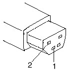
2. Remove battery pack and measure voltage between battery terminals
1 (+) and 3 (N).

|
| Pin |
Voltage (V dc) |
| 1 |
+10.0 to +18.0 |
| 2 |
Thermal Detection |
| 3 |
Ground |
|
o If voltage is less than +10.0 V dc, the battery
pack has been discharged or is defective.
o If the voltage is more than +10.0 V dc, go
to the next step.
3. Using an ohm meter, measure the resistance between battery terminals
2 (T) and 3 (N). The
resistance must be 4 to 30 kilohms.
o If the resistance is not correct, replace
the battery pack.
o If the resistance is correct, go to the next
step.
4. Install battery pack and plug AC adapter cable into computer to
charge battery pack.
o If the battery power status indicator
is blinking (orange) and battery charging indicator is on,
replace the battery pack. If the battery is charging normally, the
battery is OK.
Checking the Backup Battery
1. Carefully place the computer bottom-side up.
2. Remove the bottom cover.
3. Disconnect the battery connector from the system board.
4. Measure the voltage of the backup battery. See the following figure.
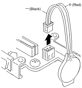
|
| Wire |
Voltage (V dc) |
| Red |
+2.5 to +3.7 |
| Black |
Ground |
|
o If voltage is correct, replace system board.
o If voltage is not correct, backup battery
was discharged by a short circuit or it is defective.
Checking the Standby Battery
Note: Make sure battery pack
is removed from computer before standby battery is removed.
1. Power-off the computer and unplug the AC adapter cable from the
computer.
2. Remove the battery pack.
3. Remove the indicator cover.
4. Disconnect the standby battery connector from the voltage converter.
5. Plug the AC adapter cable into the computer and power-on the computer.
6. Measure the output voltage at the connector on the voltage converter.
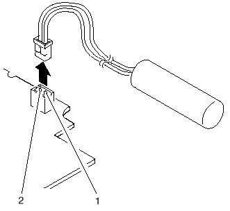
|
| Pin |
Voltage (V dc) |
| 1 |
+4 |
| 2 |
Ground |
|
o If the voltage is less than +4 V dc, replace
the voltage converter.
o If the voltage is more than +4 V dc, go to
the next step.
7. Power-off the computer and unplug the AC adapter cable from the computer.
8. Reconnect the standby battery to the voltage converter.
9. Plug AC adapter cable into computer and power-on computer. Allow
30 min for standby battery to charge.
10. Power-off computer and unplug AC adapter cable from computer -
remove standby battery.
11. Measure the voltage of standby battery.
o If the voltage is less than 3.5 V dc, replace
standby battery.
Checking the Quick Charger
If a humming or buzzing sound is heard from the quick charger
when it is operating, replace the quick charger. If the charger is operating
at a normal quiet sound level, do the following.
|
|
1. Perform steps 1 - 3 of Checking the
Battery Pack to ensure correct battery pack operation.
2. Connect power cord to quick charger and ac power outlet. Ensure
power-on indicator is on.
o If power-on indicator does not turn on, check
quick charger's power cord for correct continuity and installation.
o If the problem is not corrected, replace
the quick charger or the power cord.
3. Install the battery pack into the quick charger.
o If the charging indicator does not start
blinking, replace the quick charger.
|
Checking the Voltage Converter (700, 700C)
Use this procedure to isolate a problem with the ThinkPad
700, 700C voltage converter.
Note: If the problem only
occurs when using the computer with a good battery pack, replace the
voltage converter.
1. Power-off the computer.
2. Power-off all attached devices and disconnect them from the computer.
3. Unplug the AC adapter cable and remove the battery pack from the
computer.
4. Carefully place the computer bottom-side up and remove the bottom
cover.
5. Plug the AC adapter cable into the computer.
6. Power-on the computer.
Important: Be careful not
to actuate the suspend switch (located between the Esc key and the LCD)
during the operation. When you turn the computer upside down with the LCD
opened, put
something under the computer to prevent accidentally actuating the
suspend switch.
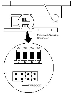
7. Check the voltages of the voltage converter on the system board.
|
| Signal |
V dc Min. |
V dc Max. |
| VA |
+4.75 |
+5.25 |
| VG |
+4.75 |
+5.25 |
| VB |
+4.75 |
+5.25 |
| VC |
+3.42 |
+3.78 |
| PWRGOOD |
+4.00 |
+5.25 |
|
Note: Only VOLT is marked
on the system board.
Use the above figure to locate the VA, VG, VB, VC, and PWRGOOD signal
names.
o If all voltages are correct, the voltage
converter is operating correctly.
o If the voltages are not correct, go to the
next step.
8. Power-off the computer and unplug the AC adapter cable from the computer.
9. Check for a short circuit between GND and VA, VG, VB, or VC.
o If there is a short circuit, replace the
following FRUs one at a time to correct the problem.
- Voltage converter
- System board
o If there is no short circuit, go to the next step.
10. Check the output voltage of the AC adapter cable (see Checking
the AC Adapter).
o If the output voltage is correct, go to the
next step.
11. Replace the following FRUs one at a time.
- Voltage converter
- System board
Checking the Voltage Converter (720, 720C)
Use this procedure to isolate a problem with the ThinkPad 720, 720C
voltage converter.
1. Power-off the computer.
2. Power-off all attached devices and disconnect them from the computer.
3. Unplug the AC adapter cable, then remove the battery pack from the
computer.
4. Carefully place the computer bottom-side up and remove the bottom
cover.
5. Plug the AC adapter cable into the computer.
6. Open LCD half-way, stand computer on its front edges so suspend
switch isn't activated.
7. Power-on the computer.
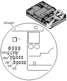
8. Check the voltages of the voltage converter on the system board.
See the following figure.
Notes:
a. Make sure the suspend switch (located to the left above the keyboard)
is not activated during
measurement of the voltage.
b. Only PG is marked on the system board. Use the following figure
to locate the VA, VG, VB,
VA3, and VB3 signal names.
|
| Signal |
V dc Min |
V dc Max |
| VA |
+4.75 |
+5.25 |
| VG |
+4.75 |
+5.25 |
| VB |
+4.75 |
+5.25 |
| VA3 |
+3.42 |
+3.78 |
| VB3 |
+3.42 |
+3.78 |
| PG |
+4.00 |
+5.25 |
|
o If any voltage is not correct, go to step
9.
o If all voltages are correct, the voltage
converter is operating correctly. If the power problem did not reoccur,
reconnect the devices removed in step 2 to isolate a device problem.
o If all the voltages are correct and the power
problem still exists, replace the following FRUs
one by one.
- System board
- Processor card
9. Power-off the computer and unplug the AC adapter cable from the
computer.
10. Check for a short circuit between Ground and VA, VG, VB, VA3 or
VB3. The following table shows which FRUs can cause a short at each signal.
o If there is a short circuit (less than 10
ohms), remove the FRUs indicated one at a time until
the short circuit disappears. Replace the FRU causing the short circuit.
| FRU |
VA |
VG |
VB |
VA3 |
VB3 |
| Voltage converter |
x |
x |
x |
x |
|
| Processor card |
|
|
x |
|
x |
| System board |
x |
x |
x |
x |
x |
| Video card |
x |
|
x |
x |
x |
| Base memory card |
x |
|
|
|
|
| Keyboard control card |
x |
|
x |
|
|
| Math coprocessor |
|
|
x |
|
x |
| Diskette drive |
|
|
x |
|
|
| Hard disk drive |
|
|
x |
|
|
| LCD |
x |
|
|
|
|
| Indicator assembly |
|
x |
x |
|
|
11. If there is no short circuit, replace the following FRUs one at
a time.
o Voltage converter
o System board
|