|
Parts and FRUs
Battery Type and Correct Orientation
Clear a Power-On Password
Removing the Assembly
Battery/Speaker Connector Pinout
Parts and FRUs
| FRU | Description |
|---|
| 33F5950 | Battery/Speaker Assembly * |
| 57F1437 | Battery/Speaker Assembly for 8565 ** |
| 72X8558 | Cable for Speaker Assembly |
| 72X8498 | Battery |
* The sticker on a spare assembly I've checked says: Assy No: 90X6878. And the
small PCB has 90X6876 etched to it.
** Model 65 SX uses a pair of Dallas chips to implement the RTC/CMOS and NVRAM
functionality. Each of these chips has its own internal battery, therefore a
standalone battery isn't needed. The unit uses a "stripped down" version of the
assembly, with no battery contacts and only a two-wire connection for the speaker.
Battery Type and Correct Orientation
|
The contacts on the battery point to the rear, where they press against the spring clips.
See the Battery Cross Reference
for the correct battery type.
|
Clear a Power-On Password
Model 50, 60, 70, 80 Override Jumper
- Power-off computer and unplug power cord.
- Remove system-unit cover.
- If speaker assembly has pins, short pins 2 and 3 together.
- If speaker assembly does not have pins, insert meter lead into connector
1 and short other end of lead to frame ground.
With assembly shorted, power-on computer. This erases power-on password.
Remove short after POST is finished.
When installed the jumper shorts the Clear POP pin to ground.
Removing the Assembly
Models 60, 65 SX, and 80
To remove the assembly, simply slide it towards the opened side of the
case.
Models 50, 50Z, and 70
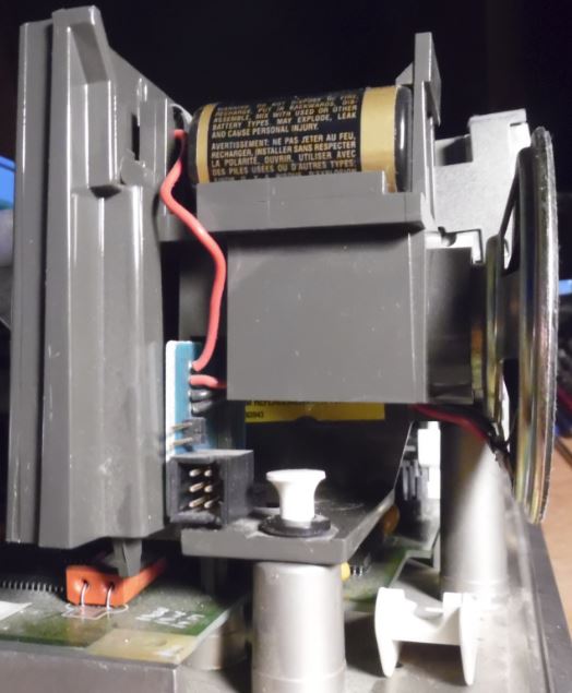
To remove the assembly, you have to first push the retaining clip at the
bottom of the assembly inwards. If you have trouble finding the clip, refer to
the following picture for its location (right over the orange crystal
holder):

While pressing it in, push or pull the assembly up, away from the base of
the machine. Please note, that in Models 50, 70 Type 1 and 70 25 MHz the
assembly is also being held in by the card edge connector on the planar
board.
Battery/Speaker Connector Pinout
Pin Header Connector (Models 50Z, 60, 70 Type 2 and 80)
6-pin header on the battery/speaker assembly PCB.

|
| Pin | Signal | Pin | Signal |
|---|
| 1 | Speaker Data | 4 | Not Connected |
| 2 | Ground | 5 | Clear POP |
| 3 | +6 V (Battery) | 6 | Not Connected |
|
Card-Edge Connector (Models 50, 70 Type 1, 70 25 MHz)
6-pin card-edge connector on the planar board.

|
| Pin | Signal | Pin | Signal |
|---|
| 1 | Not Connected | 4 | Speaker Data |
| 2 | Not Connected | 5 | Ground |
| 3 | Clear POP | 6 | +6 V (Battery) |
|
|