@8EFC.ADF IBM PS/2 Fast/Wide SCSI Adapter (Uses same ADF as SE F/W)
C8EFC.ADF Init file for @8EFC.ADF
rev71upd.exe SCSI-2 Fast/Wide Adapter Firmware Upgrade .71
corv77.exe SCSI-2 Fast/Wide Adapter Firmware Upgrade .77
corvC9.exe SCSI-2 F/W Enhanced Fast/Wide Firmware Upgrade FRU 93H7896 & 52G3380
ibm2.exe F/W and OS/2 2.1 Fix '94 (ibm2scsi.add and ibm2m57.add)
scsi2fw.exe SCSI-2 F/W Support Diskette v2.0
scsi2fw.txt Readme for scsi2fw.exe
194-145 SCSI-2 F/W Adapter/A, SCSI-2 Differential F/W Adapter/A
AN-0904 An Introduction to the Differential SCSI Interface
DS36954 Quad Differential Bus Transceiver
AN-904 Application Note 904 An Introduction to the Differential SCSI Interface
Oct.
1994 Adapter Microcode Protection during Download (TDB)
SCSIFIX.ZIP Finally! A utility
to alter the number of sectors for a SCSI drive and
convert them to a 3.94GB drive! Bob Eager, you have
answered a prayer!
Possible MCA
Interface Chip Problems
Differential
SCSI-2 Fast/Wide Adapter FRU 11H3599 /
11H7660
Rework
on 11H7660 Front
Rework
on 11H7660 Back
Enhanced
Differential SCSI Fast/Wide Adapter FRU
52G3380
Jumpers
on the Fast/Wide
68
pin Internal Connector
Drive connector
SCSI
device
and adapter configuration flexibility
SCSI Device
Order
Maximum SCSI
Devices Supported
Fast
POST Consequences
ADF
Sections
ESDI Requirements
Differential SCSI Fast/Wide Adapter "Corvette Turbo"
FRU 11H3599 (no workee) / 11H7660 (workee) (RS6K 4-6)

CR1 LED
J1 50 pin SE SCSI connector
J2 Factory use
J3 C-68 DFW
SCSI connector
J5 Leave open.
Not used.
J6 Boot Enable
J7 FW SE SCSI
connector
RN1,2,3 Used
for RS6K stuff
TR1 PTC
resistor for internal bus
TR2 PTC
resistor for external bus
|
U1 61G3929,
SCSI BIOS, Odd
U2 61G3930,
SCSI BIOS, Even
U8,9 Sony
CXK581000AM-70LL
U10 AMD
N80C186-20
U11 40.0000
MHz osc
U12 82G2645
Int SE SCSI ctrlr
U13 61G2323
MCA Bus interface
U14 52G9707
Ext Diff SCSI ctrlr
U15 empty
(unused even in RS6K)
|
RN1,2,3 Removed on
RS/6000 systems when a high-reliability configuration is
used (one of them there "Y" arrangements illegal to
normal SCSI users).
What is With the Yellow
Termpacks?
Differential SCSI uses a standard passive resistor
termination. This terminator remains unchanged from the
original SCSI-1 standard to the proposed SCSI-3 physical
layer. So you might be confused why a newer SCSI adapter
uses the older yellow termpacks like the three can
Spock.
The SCSI-2 Differential Fast/Wide Adapter/A
supports an internal single-ended and an external
differential SCSI bus.
FRU 11H3599
To date, all attempts to get this RS/6000
adapter to work in a PS/2 have failed. Although the
chipset is the same as on the Fast/Wide, the rev .71
flash update does not recognize a F/W chipset.
FRU 11H7600
This FRU with a PLCC socket WILL work with no
special poodle faking. User "No Deal" has posted images
of the Set Configuration and Set and View SCSI Devices
screens.
How Many
is Enough?
Tim Clarke uttered this after a pint of warm beer:
All **IBM** SCSI CBIOS-flavour (i.e. *not* FD
MCS700 OEM) will share IRQ14 and you only need one BIOS
ROM enabled to drive multiple adapters. So, for example
you *should* be able install (in the same slot-type,
please) IBM F+W SCSI-2 "Corvette", IBM SCSI w/cache
("Spock") and IBM SCSI w/o cache ("Tribble") in the same
PS/2. No naughties like AHA1640, Storage Dimensions unless
you disable their BIOS ROMs and assign a different IRQ.
OS Limits
Not all Microsoft products support multiple IBM
SCSI adapters gracefully. W9x cannot handle shared IRQs
and will drop into MS-Doze (In)compatibility mode.
Win NT, OS/2, Linux and other UNIX systems can handle shared
interrupts.
J7 Pinout
IBM's patent info/Tech Discovery
Bulletins, TDB
identifies
the
Burn/Alive/TXD/RXD
as being used to flash certain components. Basically,
factory use only.
Fast/Wide
in 8590/8585
If you don't have a Type 4 complex on a 95A
(dual serial/dual parallel), you may not be able to use
some features of the Fast/Wide, most notably
Internal/External Bus Mode. You need
to run SCSI2FW.EXE to
update the system partition.
FRU 11H7660
To my surprise, the 11H7660 configures
fine, flashes to .71, and works like a normal F/W.
Front 11H7660 DFW Rework
Rear 11H7660 DFW Rework
Rework A comes off the fourth MCA contact.
Rework B comes off the solder pad marked with a V.
Rework C comes off the third pin on the upper left of
U23.
Rework D comes off the second pin of U23.
Jim Shorney rains on our parade- he warns that foil
cuts may have been made in addition to the rework
wires.
Enhanced Differential SCSI Fast/Wide Adapter
FRU 52G3380 [workee] (RS6K 4-C)

CR1 LED
J1 FW SE SCSI connector
J2 50 pin SE SCSI connector
J3 C-68 DFW SCSI connector
J5 Leave open. Not used.
J6 Boot Enable
J7 Factory use
RN1,2,3 Used for RS6K stuff
TR1 PTC resistor for internal bus
TR2 PTC resistor for external bus
U1 88G1094, SCSI BIOS, Odd
|
U2 88G1095, SCSI BIOS, Even
U4 82G2645 Int SE SCSI ctrlr
U5,18 Nat'l Semi DS36954
U9,10 Sony CXK581000AM-70LL
U11 AMD AM186 EM-40VC
U12 88G1092
U13 88G1093
U16 61G2323 MCA Bus interface
U17 52G9707 Ext Diff SCSI ctrlr
Y1 40.0000 MHz osc
|
Rear of Enhanced DFW

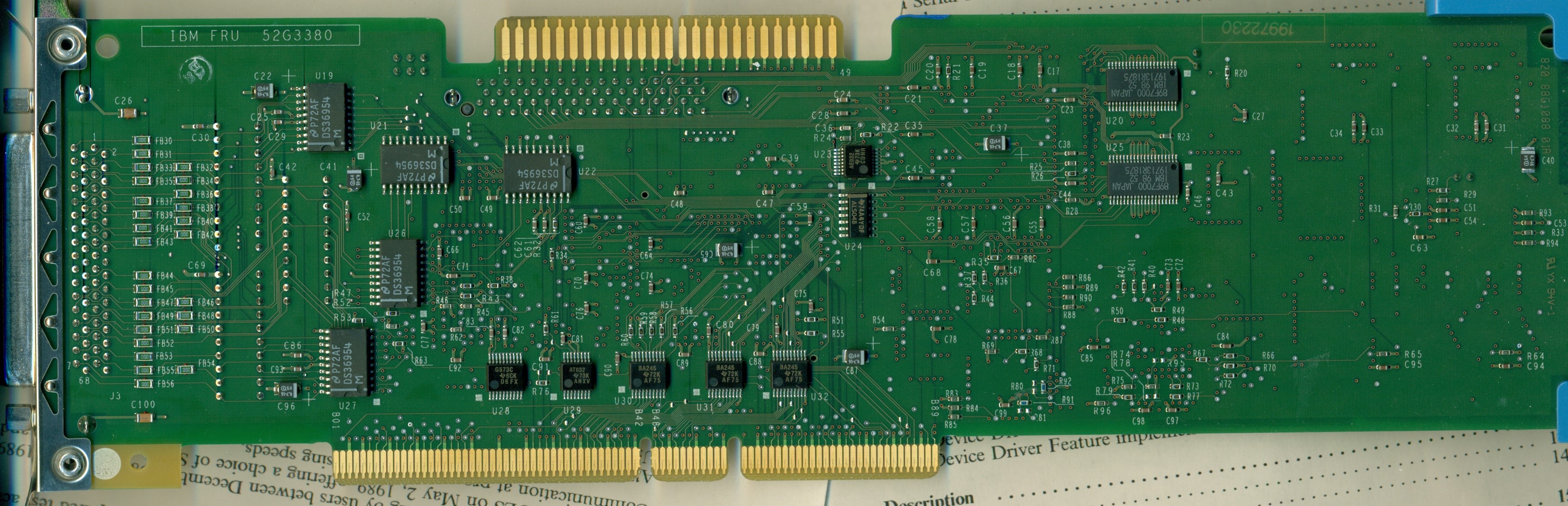
U19,21,22,26,27
DS36954
|
U20,25
89F7000 Term Network, SE |
DS36954
- Quad Differential Bus Transceiver
AN-904:
Application Note 904 An Introduction to the Differential
SCSI Interface
Why Five DS36954?
Remember, this adapter was used by AIX, and supports a
high-reliability configuration
"Five devices can implement a complete SCSI initiator
or target interface. Three transceivers in a package are
pinned out for data bus connections. The fourth
transceiver, with the flexibility provided by its
individual enables, can serve as a control bus
transceiver."
If you look at the further two DS36954 on the front (by
the yellow termpacks), it seems we would need five
complete DS36594 plus one gate from a sixth DS36594 for
16 bit SCSI, and the rest of the gates (three from the
sixth and four from the seventh) are used for control.
89F7000 Term Network, SE
These are the same parts used on the Corvette for
automatic termination of the internal Single Ended
ports.
The SCSI-2
Differential Fast/Wide Adapter/A is a dual-ported, fast
and wide (two bytes wide) SCSI Micro Channel adapter
that provides synchronous SCSI bus data rates of up to
20MBps. The internal SE port is capable of
addressing up to seven SE SCSI devices and the
differential external port is capable of addressing up
to seven differential SCSI devices, providing a maximum
of 14 devices per adapter. The number of physical
devices attached to each port is limited by SCSI bus
cabling restrictions. The external differential
port can support a total cable length of 25 meters (82
feet).
Additional system,
subsystem and high-availability connections are also
available with the differential system-to-system and
Y-cable features.
Corvette vs. Enhanced Corvette
Turbo
William R. Walsh wrote:
Quick testing in the Server 95A upgraded to P180MMX
shows a bit of a speed improvement over the standard issue
Corvette. Using a Seagate 10,000 RPM SCA hard disk and
UZ's "no-LED" driver, I got:
Corvette:
Max 11.5MBP/S
Min 10.6MBP/S
Avg 11.1MBP/S |
Enhanced Corvette
Turbo:
Max 13.7MBP/S
Min 13.0MBP/S
Avg 13.9MBP/S |
The Enhanced Corvette Turbo shows a CPU utilization
of 10.4% compared to the Corvette's 10.1%. Tests were run
using the Simpli Software HDTach tool, which was used
before during SPOCK-206 NT driver testing.
PTC
Function
There is one PTC for the internal SCSI bus
and another for the external bus. The PTC protects the
SCSI bus from high currents due to shorts on the cable,
terminator, or device. It is highly unlikely that the PTC
resistor can be tripped by a defective adapter.
A fault (short circuit) causes an increase in
PTC resistance and temperature. The increase in resistance
causes the PTC resistor to halt current flow. The PTC
resistor returns to a low resistance and low temperature
state when the fault is removed from the SCSI bus or when
the system is powered off. Wait 5 minutes for the PTC
resistor to fully cool, then reset.
MF-SM Series MF-SM150
Fixed, local copy
PLCC Socket
on Fast/Wide
The PLCC Socket U7 was possibly to provide a
RS/6000 BIOS, and the jumper J5 might have been to enable
it. Documentation for the RS/6000 says that PLCC socket is
unused. The related 4-4 [11H4779] SCSI-2 SE High
Performance Internal/External I/O Controller has a chip
(FRU 52G7507) in the PLCC socket. The 4-4 is the only F/W
related SCSI adapter to have the PLCC chip installed..
Jumpers
on Fast/Wide
The results of shorting the jumpers ranged
from no difference, slight performance hit (%10 overhead
increase) or a system-halting error. Leave them off.
RS6000 documentation says the jumpers are to be left
open.
J5
grounds out pin 33 on the internal SCSI controller
82G2645. Purpose unknown.
J6
grounds out pin 1 of U1 and U2. Marked "Boot Block
Enable"
68 pin Internal Connector on D F/W
SCSI Adapter
This is a "mini-Centronics" or a Vesa Media
Channel plug. The ANSI moniker for it is a "P" plug.
Also seems to be used for SCA drives... Hmm...
AMP (and Tyco) #
1-557089-2
Looks like THIS
or if you want the page go HERE
Newark Electronics 97F8813
CHAMP. 0.050 I Series Interface Connectors
For VMC Applications: 68-Position
Designed for use with 30 AWG solid conductors on
.064mm (.025") centers. look HERE
Molex 71660i Molex part
15-92-3068 1.27mm (.050") Pitch
EBBI™ 50D - Receptacle, Vertical, IDT 71660i
Looks like THIS
Terminates to 30 AWG solid or stranded
.025" ribbon or laminated discrete wire cable
Drive
connector
The 68 pin crimp-on device connector. Dalco 59611 $4.25
SCSI device and adapter configuration
flexibility
Systems with the enhanced SCSI device and
adapter support allow up to 8 IBM PS/2 SCSI adapters of
any type to be installed in a single system. The maximum
number of SCSI devices which many be configured in these
newer systems has also been increased from 60 to
120. However, other factors, for example, the type
of devices (optical, etc.), cooling requirements, or power
consumption of the devices may limit the number for a
particular system.
SCSI Device Order
SCSI device logical ordering and hard drive
letter assignment (e.g. C:, D:) sequence is determined
by the SCSI adapter slot numbers, internal or external
SCSI bus connection, and SCSI ID of the connected
devices.
Adapters are scanned for SCSI devices
beginning with the SCSI adapter in the lowest numbered
slot. Devices connected to the same adapter are
logically ordered according to device SCSI IDs in order
from 7 to 0 and then from 15 to 8 according to the
priority scheme defined by the SCSI standard.
Devices connected to a SCSI-2 Fast/Wide adapter's
internal bus connector are ordered logically before
devices connected to the external bus of the same
adapter.
Maximum
SCSI Devices Supported
Wide SCSI devices support 16 possible SCSI
ID values. The adapter uses one these values;
therefore, the SCSI-2 Fast/Wide adapter can connect up
to 15 fast and wide devices internally or externally in
any combination using the remaining ID values.
Narrow SCSI devices support 8 possible SCSI ID values;
therefore, up to 7 narrow SCSI devices can be connected
to the internal or external SCSI busses in any
combination using the remaining ID values. Wide
and narrow devices may be mixed on the same
internal/external bus by using the proper combinations
of SCSI bus cables, terminators, and/or SCSI connector
converter adapters.
Note:
Use of a 8 bit (Narrow) cable forces the controller to
default to only 7 devices supported on that port, even
if all devices on that cable are Wide.
Fast
POST Consequences
Some newer systems also provide a FAST POST
option which may be selected from the system
configuration menu or from the IBM logo screen.
When this option is selected, the system will not check
for the presence of newly added SCSI devices unless F1
is also pressed while the IBM logo is displayed.
Newly added SCSI devices will not be configured nor will
an error occur if the fast post option is chosen as the
default. To access the system configuration program,
press F1 while the IBM logo screen is displayed to
configure the new SCSI device(s) initially.
ADF Sections @8EFC.adf 4/10/95
I/O Address
I/O address for the adapter. Each adapter
must have a unique address range.
<3540-3547>,
3548-354F, 3550-3557, 3558-355F, 3560-3567, 3568-356F,
3570-3577, 3578-357F, 3578-357F
DMA Arbitration Level
Arbitration level used by the adapter to
transfer data.
<C>, D,
E, 8, 9, A, B, 1, 3, 5, 6, 7
SCSI Adapter Address (ID)
SCSI ID of the adapter. Usually ID7, unless
you have specific requirements.
Adapter IDs available are: <7>, 6, 5, 4, 3, 2, 1, 0
Move Mode Support
Enable or Disable Micro Channel Subsystem
Control Block Move Mode This is the second mode of SCBA
(first is locate mode) which permits the system
processor to move the subsystem control blocks to the
adapters directly.
<Enabled>
or Disabled
Wait State Support
Enable or Disable Bus Master wait states.
If the target expansion card is an older card, it may
not be able to process commands or data from the
busmaster fast enough, and when queried by the
busmaster, it replies with "not ready". By inserting a
wait state, the slower card has more time to signal
"ready". Enabling wait states can slow your busmaster
down.
<Disabled>
or Enabled
Data Parity Exception Handling
This Adapter can generate and detect data
parity on Micro Channel. Data parity must be supported
on both ends of an across-the-bus transmission in order
for this error detection process to be effective. A data
parity enable (-DAPAREN) bus line to the system and
other expansion boards is enabled when data parity is
being used. If the System does not support Data Parity
Exception Handling, this feature will always be
disabled.
<Enabled>
or Disabled
Selected Feedback Return
Exception
When enabled, the busmaster monitors the
selected feedback return and card-selected feedback
buslines. The return line tells the master that it's
target expansion board is responding properly to being
addressed for a read or write operation. If the bus
master does not receive this signal (and SFR has been
enabled) it may mean that the expansion board is not
operating properly or that the signals themselves are
not properly traveling across the expansion bus. This
error causes the master to immediately halt the transfer
in progress and notify the host system of the error
using an interrupt. Note:
The SFR must be ignored for PC compatibility. If the
System doesn't support the Selected Feedback Return
feature, it will always be ignored.
<Enabled>
or Ignored
100 ns Streaming Data Transfer
Support
This provides better performance. It will
always be disabled if the system doesn't support it.
<Enabled>
or Disabled
Target Mode
Target mode should be disabled only if this
system is sharing SCSI devices with another system and
there are more than 15 devices to be shared. Only
15 devices can be configured on each adapter.
When target mode is enabled,
this adapter appears as a processor device on the
other system and unless you have specialized software
that can communicate between the two systems through
these processor devices (peer-to-peer communication),
there is no advantage in having target mode enabled.
When target mode is disabled, this adapter does not
appear as a device to the other system, and one more
device can be shared by the two systems. If your
system is not sharing any SCSI devices with another
system on this adapter, it does not matter whether you
enable or disable target mode.
<Enabled>
or Disabled
SCSI Disconnect
Disconnect is a SCSI-bus procedure in which
a device logically stops communicating with the adapter
during certain operations and then reestablishes
communication with the adapter when the operation is
complete. Disconnect should not be confused with
the 'Presence Error Reporting' option for a device in
'Set and view SCSI device configuration.' If you
are using an operating system that is single-threaded
and issues commands to only one device at a time (such
as DOS or Win95),
disabling SCSI disconnect might result in a slight
performance improvement. If your operating system
is multi-threaded (such as OS/2), disabling SCSI
disconnect will degrade the performance of the SCSI
subsystem.
<Enabled>
or Disabled
Fast SCSI - External
If Fast SCSI devices are attached externally,
enabling Fast SCSI improves performance.
- One external SCSI device enclosure model
3511.
- Up to three external SCSI device enclosures
model 3510.
- Any external configuration where SCSI cable
length isn't > 3 meters.
<Disabled>
or Enabled
Wide SCSI messages - External
'Enabled' unless Wide SCSI devices are
attached through a narrow external interface
cable.
<Enabled>
or Disabled
Wide SCSI messages - Internal
'Enabled' unless Wide SCSI devices are
attached through a narrow internal interface cable.
<Enabled>
or Disabled
Internal/External Bus Mode
'Separate', SCSI devices on external SCSI
bus connector can have the same SCSI ID setting as other
SCSI devices connected to internal SCSI bus
connector on the same adapter.
'Combined', all devices connected to
this adapter must have unique SCSI ID settings
regardless of which SCSI bus connector is used to attach
the devices. Default is 'Separate' unless you are
using an operating system device driver that does not
support independent operation of the internal and
external SCSI busses on the adapter.
<Separate>
or Combined
Note: SCO Unix and
Banyan Vines can not recognize devices configured on the
SCSI-2 F/W Adapter (DFW as well), when in a 90 /95 level
3 BIOS or higher. This is due to the the internal
and external ports beinge separated. A special
version of the SCSI-2 F/W Adapter's ADF
(@8EFC.ADF) file is available to allow the busses to be
set to a COMBINED state, which overcomes this problem.
Note: I don't
know what version this is for, nor do I know if later
versions of SCO Unix and Banyan Vines fixed this issue.
The last version of the F/W ADF has "COMBINED" as a
choice.
System Determined
ROM Address Range
Address of the 32K block of memory assigned
to the adapter. Only one SCSI Adapter will have the ROM
assigned, and any other SCSI Adapter installed will
share that address range.
ESDI Requirements
If the ESDI adapter is also installed, then
the address of the SCSI adapter must be greater than the
ESDI adapter address.
ESDI
Requirements
If the ESDI adapter is also installed, then
the address of the SCSI adapter must be greater than the
ESDI adapter address.
|