|
Constructed and described by Ron Bean. Edited by Major Tom.

Figure 1: Model-M Keyboard adapter box
This was inspired by John Szybowski's keyboard page
(archived,
local copy).
Instead of modifying a cable, I put the parts in a separate box so I wouldn't
have to worry about strain relief-- if anything happens to the cable I can
just replace it without re-doing all of the soldering. In theory this will
just sit on the floor behind my desk, but you never know what might happen...
Bill of Materials
| Qty |
Description |
Digi-Key Part# |
Price Each
(March 2004) |
Total
Price |
| 2 |
6-pin mini-DIN connector |
CP-2660-ND |
$1.38 |
$2.76 |
| 5 |
4.7K resistors (min order 5 pcs) |
P4.7KW-1BK-ND |
$0.172 |
$0.86 |
| 1 |
ABS Plastic Box 3.3x2.2x0.8" |
HM362-ND |
$4.32 |
$4.32 |
| 1 |
Male-Male PS/2 keyboard Cable |
AE1119-ND |
$2.41 |
$2.41 |
|
Handling charge for orders under $25 |
|
$5.00 |
$5.00 |
|
|
|
Total |
$15.35 |
The small-order handling fee increases the cost by 50%, so it would help a
lot if you could order at least $15 worth of other stuff at the same time
(their catalog has over 1200 pages, there must be something else you need :-).
Note that a PS/2 extension cable purchased locally costs $10, so the cost of
this project is really not excessive.
Digi-Key ships worldwide, but there is an additional $6.00 handling fee
for orders going outside the US and Canada. The good news is that if you're
in the US or Canada and pre-pay with a check or money order, they won't
charge you for shipping (there is a PDF order form on their website that you
can print out and mail in).
Note that the Male-Male PS/2 cable is probably not a stock item at your
local computer store, so be sure to order one (I've never seen a male
panel-mount PS/2 connector, so the more common male-female extension cable
won't work).


Figure 2: PS/2 connectors
Digi-Key lists three kinds of panel-mount PS/2 connectors: one metal,
one plastic, and one with wire pigtails. I recommend the plastic one, because
I ended up drilling out the mounting holes to take standard 6-32 machine screws
(smaller screws may be stock items in the electronics industry, but I didn't
have any).
I'm not sure if the metal one was intended to be mounted with the flange
on the front or the back of the panel. If you mount it on the front,
the little plastic tabs around the base would require a rather large
mounting hole, unless you want to file them off (the plastic one also has
these tabs, but the mounting flange is molded around them). If you mount
it on the back, you would have to pay attention to the thickness of the
panel and the diameter of the plug. The plastic one is made to mount
behind the panel.

Figure 3: Layout for mounting holes

Figure 4: Pilot holes drilled

Figure 5: Main mounting holes drilled
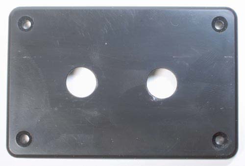
Be careful drilling soft plastic with
large twist drills-- they like to "grab" and the holes may not come
out perfectly round. I cleaned them up with a handheld taper-reamer
(available at many hardware stores, a good investment if you don't have
one). For the screw holes I just used an oversized drill bit (5/32").

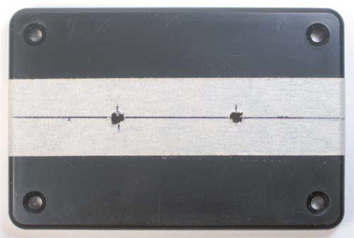
Figure 6: Sockets taped in place
I taped the sockets in place and drilled through the mounting flange
and panel at the same time. For each socket, I dropped a screw into the
first hole before drilling the second one, just to make sure nothing moved.
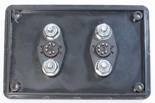
Wiring will be easier if you mount both sockets facing the same direction.

Figure 7: Sockets bolted in place

Figure 8: Wiring in place
It's been a while since I soldered anything, so I used
the extra metal socket shown above for practice. Fortunately, the
electrons don't care what it looks like. I connected a resistor from +5v to
the clock line on one connector, and from +5v to the data line on the other
one, so no pin had more than two wires on it. Even then, it gets
crowded. It helps to use thin solder that melts as soon as the joint is warm.
The crud on the back of the socket is flux from the rosin-core solder.
Model "M" Mod for Modern PCs
+5V       4 o---o----o--------->  red
                |    |
               +++  +++
               | |  | | 4K7 Ohm
               | |  | |   to
               +++  +++ 10 KOhm
                |    |
KBCLOCK   5 o---o----+--------->  green
                     |
KBDATA    1 o--------o--------->  yellow

GND       3 o------------------>  black
PS/2 Plug To Keyboard
                6  x U o  5
                4  o | o  3
                2   x o   1

               Mini-DIN Plug
    (rear side view on the solder pins)
     x-marked pins are N.C. or missing
The colors noted are taken from a Non-IBM keyboard with a fixed cable,
which is from the technical aspect like a "M" keyboard.
ASCII-Art (C) 2010 by Peter H. Wendt, Edited by Major Tom.
|