|
8590/95 Processor Board Installation (Blue Levers) (H105822)
Unsuccessful 50 MHz Processor Installation (H097075)
8590/95 Processor Board Installation (Blue Levers) (H105822)
God Emperor of Micro Channel said:
Any mention of using the Blue Levers alone to seat the complex
is a TRAP!
There is a short mention in the PC Mag, Feb 26, 1991, page 301:
"Ironically, the IBM Processor Complex requires so much pressure to
insert that IBM has attached special levers at either end of the
Processor Complex board to allow you to force it into it's socket."
This is NOT SO! Here is IBM's view of the proper procedure:
Model 90 and Model 95 systems may experience highly intermittent and
difficult to diagnose system problems due to processor boards which have not
been fully seated into the system board socket.
Caution! They can also be damaged if the complex's
edge connector is NOT inserted in the double wide Complex slot (especially in
the Model 95) -AND- the blue levers are forcibly seated.
Note: I have personally ripped off a resistor
network on a P90 complex where the edge connector was hanging BELOW the Model
95 complex slot... Used MUY MACHISIMO to seat the complex using only the blue
levers and had the outer edge of the complex slot shear off the resistor
network off of the complex...
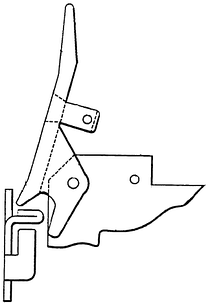
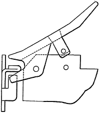
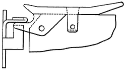
These processor boards have "Levers" on the corners of the board. The
purpose of the levers is to remove (unseat) the board from the planar. The
levers should never be used >alone< to install
or re-install the board.
17 to 22 pounds of force are required to fully seat the processor board into
the system planar. Attempting to install the board using the levers may produce
a "Snap" or "Pop" which is assumed to be the sound of the board seating. This
is often misleading.
The correct technique is as follows:
First, line up the complex so the edge connector begins to enter the complex
slot while lining up the levers to "engage" their contact points. The levers
should stick straight out away from the planar.

Then, place the heel of the hand in the center of the board and press
firmly. Model 90s are well laid out for this, But the Model 95 is special. Lay
the Model 95 down on the side AWAY from the side wall -OR- support the system
unit with the other hand while applying the insertion pressure.)
MAJ Tom said:
The Model 95 planar has a
support structure (plastic frame) on
the opposite side of the processor complex slot (and also behind all MCA slots
and SIMM sockets). This structure sits between the planar and the metal chassis
to prevent flexing during complex or adapter insertion.

Note: After ensuring that the complex's edge
connector is inside the complex slot -AND- the blue lever hooks are under the
case latches, use one hand to push the complex mostly home. You can start on
one side, then go to the other. One the complex has partially seated, you can
finish seating it with the blue levers.

MAJ Tom said:
I then push on the top edge of the complex PCB to ensure it's
fully seated. Different machines and complexes have slightly different
tolerances and in some cases the complex can't be fully seated just by using
the levers. No high force is needed for this final push - the spring contacts
are already compressed at this point. I finish by doing a visual inspection of
the installed complex.
To Remove Complex
Grasp both latches and pull up with a deliberate speed. No need for
lightning fast movements... You can do them one at a time if you have to. You
will feel the resistance drop off when the complex is free.
|