|
Available Bays
Installing Drives
RAID Bay PCBs
RAID Bay PCB
Bottom RAID Bay PCB
TL-SCSI285
Power Microswitch
Remove RAID Bay
Jumpers on Hot Swap Drives
Drive Replacement
Drive Removal
Drive Insertion
RAID without Bays 'n Trays
Available Bays
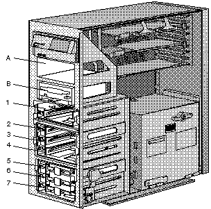
Installing Drives
1. Find the bay in which you plan to install the drive assembly.
If a drive assembly is already installed in the bay you plan to
use, remove the drive assembly as described in steps 3 and 4 of Removing
Internal Drives.
Note: The figures that accompany these steps show the installation occurring
in bay 1. These instructions also apply to bays 2 through 7.
2. Prepare the bay for installation of the drive assembly:
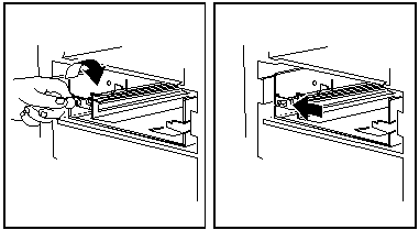
a. Insert a small coin into the slot of the small knob located on the
left-hand side of the bay. (Do not use more than light pressure to do this!
You can snap one "ear" off of the knob. Personal experience)
b. Turn the knob clockwise, one-quarter (1/4) of the way.
c. Slide the knob to the left.
d. Continue with the next step.
3. Install the hard disk drive assembly into the bay:
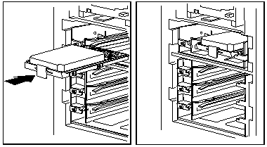
a. Position drive assembly so the connector is facing rear of server.
b. Align tray with guides, and slide the drive assembly into the bay.
c. Slide the knob to the right until it clicks into place.
Bay parts and their P/Ns
The bay mounting rails are PN 61G3839
The plate that the microswitches are attached to is 60G9814
The blue rod is 42G0033
The bay itself is 42G0026
RAID Bay PCBs
The PCBs differ in the lack of termpacks and SCSI ID circuitry on the bottom
PCB and the SCSI ID jumper on the top PCB. The single drive RAID bay uses the
top PCB 61G3843.
RAID Bay PCB 61G3843

Bottom RAID Bay PCB 61G3843

IC1 LTC1155 Dual MOSFET driver
IC2 TL-SCSI285N SCSI termination regulator
P1 Molex power connector
P2 2-pin header to microswitch
|
P3 3x2-pin SCSI ID jumper header
RP1-4 Resistor Networks
Q1,2 IRFZ48 MOSFET
|
P3 3x2-pin SCSI ID jumper header - the
top bay has a jumper on the left pair, the middle has a jumper on the middle
pair.
TL-SCSI285 - Regulator for Active SCSI Termination
TL-SCSI285 Fixed-voltage
regulator for SCSI active termination
The TL-SCSI285 is a low-dropout (0.7 V) fixed-voltage regulator specifically
designed for SCSI alternative 2 active signal termination. The TL-SCSI285 0.7 V
maximum dropout ensures compatibility with existing SCSI systems, while
providing a wide TERMPWR voltage range. At the same time, the ±1%
initial tolerance on its 2.85 V output voltage ensures a tighter line-driver
current tolerance, thereby increasing the system noise margin.
The fixed 2.85 V output voltage of the TL-SCSI285 supports the SCSI
alternative 2 termination standard, while reducing system power consumption.
The 0.7 V maximum dropout voltage brings increased TERMPWR isolation, making
the device ideal for battery-powered systems. The TL-SCSI285, with internal
current limiting, overvoltage protection, ESD protection, and thermal
protection, offers designers enhanced system protection and reliability.
When configured as a SCSI active terminator, the TL-SCSI285 low-dropout
regulator eliminates the 220- and the 330- resistors required for each
transmission line with a passive termination scheme, reducing significantly the
continuous system power drain. When placed in series with 110- resistors, the
device matches the impedance level of the transmission cable and eliminates
reflections.
Power Microswitch
Removing Microswitch Panel from 3 Bay Cage
First, take off the left rail. Then, unscrew the two screws marked
with the red arrows.
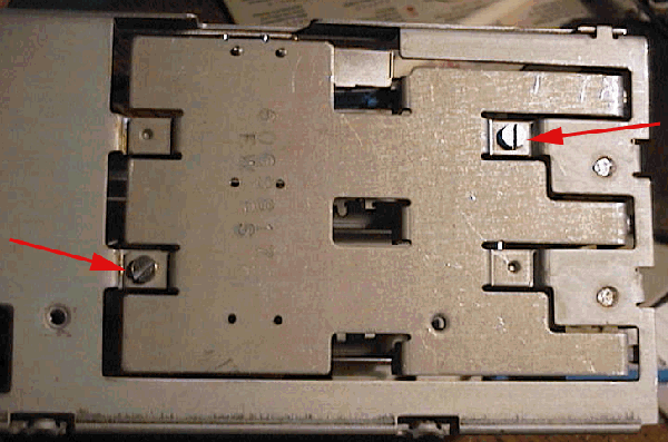
Arrow #1 points to the proper assembly of the guide and the switch lever.
The curved spring pushes down against the microswitch's lever.
Arrow #2 points to the support that limits the lever's downward travel.
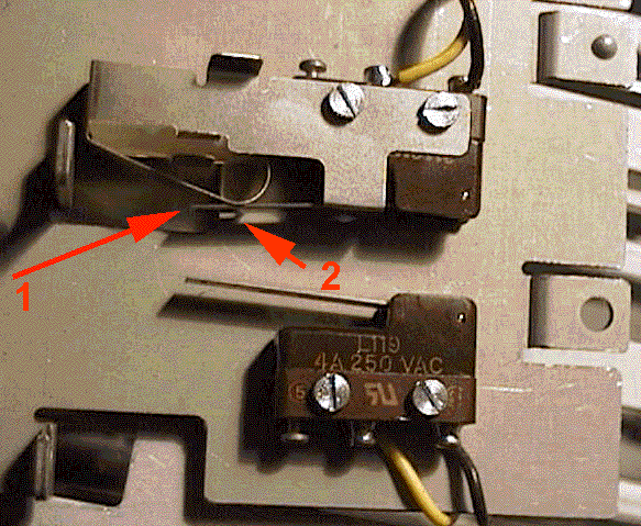
It makes it easier reattaching the switch if you start the screw
by the black wire first. That spring steel part that wraps around the switch
wants to open up. (the bottom switch is mounted reversed and without a
whatever the hell that thing is...
Microswitch Configuration
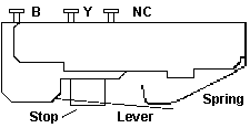
311SM702-T is an active number right now, but I do not
see the travel limit stop or the curled spring.
The switch is marked L119 4A 250VAC, 311SM702-T made by MICRO
Black wire goes to the left terminal "B", yellow wire goes to "Y".
The lever rests on the stop. If you have the lever below
it, then your switch will stay "on" regardless of how you turn the blue
knob on the Hot Swap (HS) tray. The spring rides on top of the lever, forcing
it down.
Remove RAID Bay

Single drive bay shown, three drive bay similar.
Both the three drive and single drive RAID bays have the
spring catch on the right side of the bay, facing to the side wall. So
to remove a bay, remove the SCSI cable, and unplug the power cable from
the PSU. Press in the catch and push the bay out of the DASD structure.
Jumpers on Hot Swap Drives
Some fixed disk options for the 9595 RAID system, were
shipped with the SCSI bus termination, address, and auto-start jumpers
still installed on the drive. When added to a system, the option should
not have these jumpers installed (enabled).
The excess terminators will cause signal degradation
and may result in highly intermittent and difficult to diagnose system
configuration errors or operating system failures.
The 9595A RAID ARRAY system is manufactured with
a 3 fixed disk configuration. A total of 4 additional fixed disk options
may be installed. No address or termination jumpers should be installed
on any of the additional option fixed disks. These options will be automatically
addressed and correctly terminated by the "hot plug rack" which is part
of the basic 9595A RAID ARRAY system.
The auto-start jumper should not be installed because
it allows the drive motor to spin-up immediately with system power-on.
The jumper allows a choice of either the motor starting immediately with
system power-on, or to be sequence started one at a time by POST. The total
starting surge current of all the fixed disks starting simultaneously may
cause the system power supply to "self-protect"* by shutting down.
Note: The 9595A power supply, and
other PS/2 system power supplies are designed to "self-protect" if
current surges beyond certain limits are exceeded. As options are added,
the power supply may be unable to provide sufficient starting surge current
for all drives during initial power-on. In this case, the power supply
"self-protect" will activate, resulting in the system shut down. This may
be corrected by removing the Auto-Start jumper from all the option drives.
The "self- protect" action by the power supply will not cause damage.
Drive Replacement
The IBM SCSI and RAID adapters have been designed to allow hard
disk drives in hot-swap bays to be removed or installed while the system
is running. In some situations, hard disks may be powered down by
a RAID Adapter prior to their removal from a hot-swap bay (e.g. failed
disk drive); however, this is not a fundamental requirement prior
to removing a drive. Only persons trained and knowledgeable in RAID Array
service procedures should attempt to service this type system, due to the
exposure to possible customer data loss.
When removing drives which are still running, extra care needs
to be taken. The following facts should be understood:
- The drive needs to be part of a FAULT TOLERANT
RAID 5 or RAID 1 Array or the operating system may be unable to access
data after the disk drive has been removed.
- Only RAID 1 or RAID 5 Arrays allow dynamic rebuilding
on a drive that has been replaced.
- Only one disk drive can be rebuilt at a time.
- The current level of RAID Administration Utility
for the specific operating system should be run during disk drive removal.
The RAID Adapter marks the drive DDD in this Utility to indicate a command
was issued to the drive with no response.
- Once a drive's status appears as DDD, a
replacement drive can be inserted into the bay. An operator can force a
drive which has already been removed from a hot-swap drive bay to be marked
DDD by invoking the Drive Information option in the RAID Administration
utility. This option is available in all operating systems.
- Fixed disk drives are fragile. Care should
be taken to avoid rough handling of these devices. Care should also be
used when plugging and unplugging hot swap drives to prevent damaging connectors,
etc. Use ESD procedures.
When not installed in a system unit, drives
must be protected by being packed in an antistatic bag and option/FRU pack
or equivalent. When drives are being handled outside of their packaging
the must not be subjected to a shock greater than the equivalent of being
dropped 1 inch onto a hard surface. Any shock greater than this level may
damage the disks within the fixed disk assembly and could also result in
motor bearing damage which may result in noisy operation.
- When power is removed from a hot swap drive
by the RAID Controller or by user action, the drive will immediately
park the heads, lock the actuator in the "landing zone", and begin spinning
down. However, the disk spin-down may require up to 20 seconds after power
removal. Moving the drive during spin-down should be AVOIDED.
In the event a drive is to be removed
from or inserted into a hot-swap bay, the following procedures should be
followed.
Drive Removal
If drive is being used in a hotplug application
in a 9595A system and is being removed for any reason, it must not be pulled
out of the hotplug bay immediately after opening the blue retaining latch.
Power will still be applied to the drive and the drive media will still
be spinning up until the point when the retaining latch is opened. To avoid
possible media damage, allow 10 seconds between opening the retaining
latch and removing the drive.
If the drive is being used in an 8641 / Server
500 system, power to the drive motor will be removed automatically in the
event of a drive becoming DEFUNCT and the drive may, therefore, be
removed immediately. If the drive is being used in an 8641 / Server 500
system and there is a need to remove a drive which is NOT shown as DEFUNCT
while the system is operating, the following method should be used:
- Unlatch hotplug drive and gently pull drive forwards until it can be felt
disconnecting from connector on hotplug backplane (Approx. 10mm, or 1/4 inch,
of movement).
- Allow 10 secs for motor spindown.
- Pull drive completely out of hotplug bay.
Drive Insertion
- Ensure the current RAID Administration Utility is running for the specific
operating system.
- Verify the hot-swap bay where the drive is being inserted appears as DDD
in the RAID Administration Utility.
- Carefully insert the drive into this hot-swap bay.
- Gently seat the drive completely in the backplane connector and latch the
drive into the bay.
- Follow the directions that came with the system documentation or RAID
Adapter to activate the new disk drive and/or begin a data rebuild operation.
On IBM systems, where a Hot-Spare drive is available, the data
rebuild operation will begin automatically without the requirement to replace
the failed drive. In cases where a Hot-Spare drive is not available, the
user or system administrator must use the RAID Administration Utility to
initiate the drive rebuild operation.
As stated earlier, this procedure may differ from implementation
by other vendors. Some other vendors' systems may rebuild data automatically
when a new drive is inserted. Our procedure requires the user to request
the data be rebuilt through the RAID Adapter Utilities in the case where
a hot spare drive is not available. This provides the flexibility to reuse
the remaining drives as part of another array without performing a rebuild
operation, or to start and monitor the rebuild operation when it is convenient
for the customer. If automatic unattended rebuild support is desired, then
a Hot-Spare drive should be defined.
Note 1:
It is recommended that RAID system users periodically
perform an "Array Synchronization" (perhaps twice a month) in order to
help prevent future rebuild failures. This can be done either via the standalone
RAID Adapter Support Diskette in an off-line mode, or while the server
is running via the Netfinity RAID services menu.
Note 2:
In situations where RAID hot-swap "demonstrations"
are being conducted, it is important that Drive Synchronization be done
prior to forcing a drive "dead" via a "hot-pull" of a working drive.
The drive that was pulled "hot" must then
be either replaced into the array and completely rebuilt, or it must
be configured into another array and synchronized prior to being used to
store data. This is because the act of "hot-pulling" a disk could result
in a partially written sector which would then need to be re-written to
correct the ECC bytes or else that partially written sector could cause
a rebuild failure later, if used in another array that was not completely
synchronized.
RAID without Bays 'n Trays
From Peter:
I used a 7-drop cable from an 9585 on the first
(inner) channel of the Passplay. Installed six HDs and one CD-ROM drive
with the IDs running 0 - 6 ... and the Passplay did recognize only the
"bays 1 - 4" which correspond with the drive IDs 0 - 3 (0 is the CD-ROM,
IDs 1 - 6 are HDs).
Then I plugged the cable to the second (rear) channel
- and it did show only the bays 5 - 7 (lower triple) - but shows the drive
infos for the devices installed at IDs 1 - 3 and not ID-0 (the CD-ROM)
!!. After that I set the drives to 0-1-2-3 (CD, HD1, HD2, HD3) connected
to inner channel and 1-2-3 (HD4, HD5, HD6) connected to the outer channel
using a second cable.
The drive cages from a 9595A "Array" machine are designed to
send the IDs 1, 2 and 3 - given that the drives are wired properly with
using the thin "drive addressing cable". (Ed. that's part of the drive tray)
One cage in the top 5.25" bay, one in the lower
5.25" bay and using the proper "server 95 internal cables" result in the
IDs 1,2,3 for the top cage, 5,6,7 (!!) for the lower cage (and ID-0 for
the CD-ROM in the single Half Height 5.25" bay). See the table below for
some "visual aid" on the SCSI-ID confusion.
So obviously the two "channel" connectors are predefined, the
first connector uses the IDs directly with ID2 fixed masked to "0", while the
second connector has the ID2 bit fixed set to "1" here.
This leads to the following dependency:
421 = Binary ID-values            | Bay # |
000 = ID-0 = CD-ROM               |   1   |
001 = ID-1 = Top Cage,    drive 1 |   2   |
010 = ID-2 = Top Cage,    drive 2 |   3   |
011 = ID-3 = Top Cage,    drive 3 |   4   |
101 = ID-5 = Bottom Cage, drive 1 |   5   |
110 = ID-6 = Bottom Cage, drive 2 |   6   |
111 = ID-7 = Bottom Cage, drive 3 |   7   |
Attention: These "IDs" in the list above used here
are the ones the controller "sees". Not the ones that are really represented
through the device SCSI-ID jumpering. ID-7 under normal circumstances is used
for the SCSI controller itself - and in fact the "seen" IDs seem to be remapped
somehow. See the binary values to explain the dependencies between position
and ID sent back to the controller.
This list proves that the ID4 bit is used to differ between
"upper" and "lower" triple pack.
|