|
194-377 Options by IBM: Processor Upgrade Products (PDF)
S83G-8275 Options by IBM Hardware Maintenance Manual Supplement
Lightning 486 Installation Guide 486/BL66 for PS/2 Models 70 & 80
(Kingston)
IBM PS/2 Blue Lightning Processor Upgrade (txt)
Note: You must use 8570/80 Reference Diskette Version 1.10 or later.
Blue Lightning Utilities
Different formats but the same contents - a set of utilities and batch
files that allow you to disable/enable the Lightning 486 cache:
blc_util.exe Blue Lightning utility diskette (self-extracting disk image)
blc_util.zip Blue Lightning utility diskette (zipped image)
Lightning_486bl66 Kingston 486/BL66 for 8570/8580 utility diskette (self-extracting archive)
To control cache speed under OS/2 or DOS (but not in a DOS session under
OS/2), run FAST or SLOW from the command prompt:
- Type slow to disable BL cache
- Type fast to enable BL cache
To permanently affect caching options, use SW-1 on bank 1.
Proper Numbers
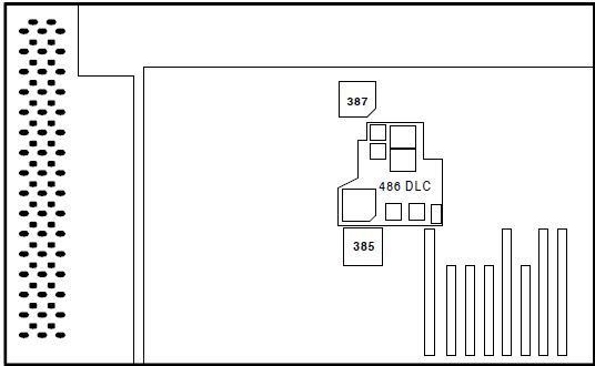
"The mentioned P/N 71G2610 is wrong. This is the Reply "Model 60/80 Upgrade
Board" P/N. Look HERE. The
correct numbers are
HERE.
FRU P/N ASM P/N  DESCRIPTION                   OPTION P/N
------- -------- ----------------------------- ----------
13H6701 78G2528  486DLC2 PROCESSOR FRU 13H6698 OP7080Y
Wolf says: I have another one on my 70/80 486DLC2 upgrade: 78G4583
"IBM PS/2 - Processor upgrade options, Applicable to: EMEA"
So, it might be possible the tip does not apply in the US?
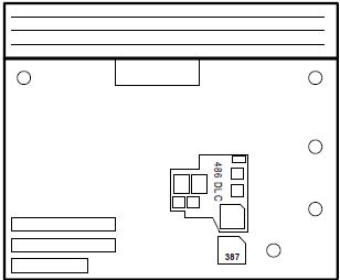
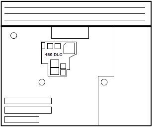
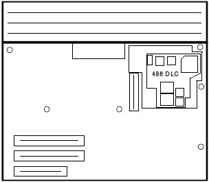
486DLC2 System Board Upgrade
FRU P/N 13H6698
FRU P/N 13H6701, P/N 71G2610
P/N 78G4583 (assy?), 78G4585 (PCB?), FCC ID ANO71F3164
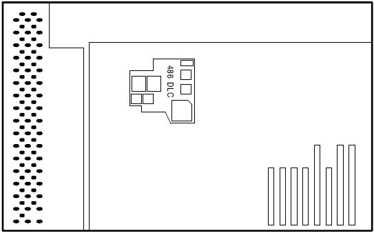
![[P]](/other/img/photo.gif "Front")
|
|
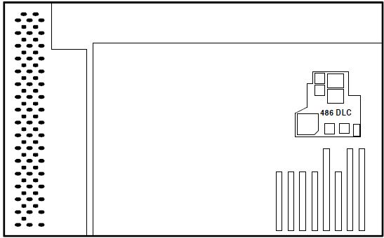
|
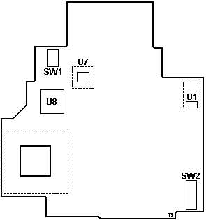
SW1 Switch Bank 1 (4x)
SW2 Switch Bank 2 (6x)
U1 TL7702AC Supply-Voltage Supervisor
U7 66.666 MHz osc
U8 Hypertec HYP0401 (data buffer?)
|
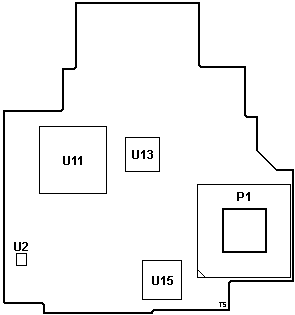
P1 PGA-132 plug
U2 LT1117 Voltage Regulator
U11 IBM 50G3589 486DLC2-66 CPU
U13 Hypertec HYP0401 (data buffer?)
U15 Hypertec HYP0301
|
U8,13,15 Hypertec ASICs; The same chips
as on the Hypertec 50Z Upgrade. The chip
labeling was painted over with a black sharpie. (IBM trying to obscure the true
origins of the upgrade?)
The Blue Lightning 486BL2 is an integrated 32-bit CPU with a 486 instruction
set, a 33/66 MHz clock, and 16KB of cache. The clock-doubling speed and
internal 16KB cache may enhance performance up to seven times over a 386DX
processor (depending on application). The 486BL2 CPU uses an optimized
instruction set and supports an enhanced CISC architecture ensuring
compatibility with this architecture.
The 486BL2 allows for a Math CoProcessor for non-integer application
performance. It also supports bus mastering adapters, if they are present in
system.
Note: To be sehr klar, the 486DLC2 / 486BL2 does
NOT have an FPU, and requires a math coprocessor / NPU / FPU / 387DX with a
speed equal to or higher of the host system. Example: Your 8580 has a 20 MHz
system speed. FPU must be rated for at least 20 MHz. You can drop in a 387DX-25
into a 20 MHz system, but it will only run at the system speed of 20 MHz.
Important: Always run Diagnostics with Blue
Lightning Processor Upgrade cache disabled. (BANK-1 SW-1 OFF = cache disable
for testing purposes!)
486DLC2 Upgrade Supported Systems
Model 70 (8570) A16, A21, A61, A81, E61, 061, 081, 121, 161
Type 1 planar covers entire base, battery assembly plugs into planar. Note: NO extender!
Type 2 planar does not cover entire base, a cable connects battery assembly to planar.
Type 3 planar covers entire base, CPU board under floppy, battery assembly plugs into planar.
Model 80 (8580) A16, A21, A31, 041, 071, 081, 111, 121, 161, 311, 321
Type 1 - most 16 MHz, some 20 MHz planars.
Type 2 - most 20 MHz, some 16 MHz planars. Note: Extender NEEDED!
Type 3 - 25 MHz planars (386DX "A" series).
132-Pin PGA Socket Extender
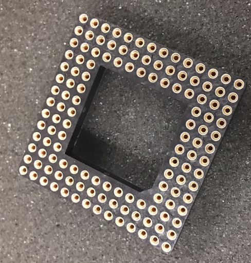
The 132-pin PGA Socket Extender is required on 8570 Type 2 and 3 planars,
and on 8580 Type 2 planars, in order to raise the Lightning 486 board above
components on the planar.
Note: Extender is not needed on a Model 70 Type 1
or Model 80 Type 1 or 3 planar.
80386DX chip extractor tool
Switch Bank 1 Default Switch settings
| SW-1 |
SW-2 |
SW-3 |
SW-4 |
| ON |
Off |
Off |
Off |
Switch Bank 2 Default Switch settings
| SW-1 |
SW-2 |
SW-3 |
SW-4 |
SW-5 |
SW-6 |
| ON |
ON |
ON |
Off |
ON |
Off |
Switch Bank 1 function
| SW # |
Setting |
Controls |
Remarks |
| 1 |
ON (D)
Off |
Cache on at startup
Cache off at startup |
B1S1 – Enable cache at startup |
| 2 |
ON
Off (D) |
Flush cache on INT 9
Do not flush cache on INT 9 |
B1S2 – Flush cache on INT 9 |
| 3 |
ON
Off (D) |
Flush cache on INT 10d
Do not flush cache on INT 10d |
B1S3 - Flush cache on INT 10d |
| 4 |
ON
Off (D) |
Flush cache on INT 11d
Do not flush cache on INT 11d |
B1S4 - Flush cache on INT 11d |
B1S1
- Enable cache at startup. All system memory
(up to 32 MB) is automatically cached and the cache may
be turned on or off from startup. Caching should always
be enabled from startup unless you have a particular
software application which will not load with caching
enabled. This switch is only read at power on, not on a
warm boot (Ctl+Alt+Del).
B1S2
- Interrupt Cache Flush Enable - cache is flushed
whenever INT 9d occurs.
B1S3
- Interrupt Cache Flush Enable - cache is flushed
whenever INT 10d occurs.
B1S4
- Interrupt Cache Flush Enable - cache is flushed
whenever INT 10d occurs
Note:
Interrupt Cache Flush Enable - This can be OFF for all
Type I and Type II systems for optimal performance. For
Type III systems with Bus Master Adapters, Interrupt
Cache Flushing should be ON for those IRQs used by the
Bus Master Adapters in the system. Adapters that use PIO
should not need to enable flushing the cache as they do
not use IRQs.
Important: Always
run Diagnostics with 486/BL66 cache disabled. (BANK-1
SW-1 OFF = cache disable for testing purposes !)
Switch Bank 2 function
| SW |
Setting |
Controls |
Remarks |
| 1 |
ON (D)
Off |
Flush cache on INT 14d
Don't flush cache on INT 14d |
B2S1 Interrupt Cache Flush Enable INT 14d |
| 2 |
ON (D)
Off |
Fast RAM count
Slow RAM count |
B2S2 Cache adapter card ROMs
|
| 3 |
ON (D)
Off |
Cache all extended memory
No caching 14MB - 16MB |
B2S3 memory mapped devices > 32 MB |
| 4 |
Off (D) |
(Reserved) |
B2S4 Enable write pipeline (network)
|
| 5 |
ON (D) |
(Reserved) |
B2S5 Flush L1 cache w/ XGA - XGA2 |
| 6 |
ON
Off (D) |
Flush cache on INT 15d
Don't flush cache on INT 15d |
B2S6 Interrupt Cache Flush Enable INT 15d |
B2S1 -
Interrupt Cache Flush Enable - cache is flushed whenever
INT 14d occurs.
B2S2 - The
default (ON) caches adapter card ROMs for faster RAM
count and is only active before system boots. If system
stops after memory count completes, try turning this
switch OFF. The RAM count will be slower, but system
performance after boot will not be adversely affected.
B2S3 - The default
(ON) allows for memory mapped devices above 32 MB of
extended memory and allows for normal RAM in the 14 to
16 MB region. Set to OFF if a memory mapped device (i.e.
XGA video adapter) is located in the 14 to 16 MB region.
B2S4 - The default
(OFF) enables a write pipeline to absorb CPU writes into
a buffer to reduce CPU wait states. If you are connected
to a network and experience problems, turn Bank 2 Switch
4 to ON.
B2S5 - The default
(OFF) does NOT flush cache on writes to C000-DFFF. For
XGA / XGA-2 adapters, set Bank 2 Switch 5 to OFF to
flush the cache on writes to C000-DFFF. In order to
maintain video integrity, the L1 cache needs to be
flushed when the 486/BL66 detects writes to the
C000-DFFF region.
B2S6 -
Interrupt Cache Flush Enable - cache is flushed whenever
INT 15d occurs
Note: Interrupt
Cache Flush Enable - This can be OFF for all Type I and
Type II systems for optimal performance. For Type III
systems with Bus Master Adapters, Interrupt Cache
Flushing should be ON for those IRQs used by the Bus
Master Adapters in the system. Adapters that use PIO
should not need to enable flushing the cache as they do
not use IRQs.
XGA Video Adapters
If your XGA / XGA2 is unable to run in XGA display mode,
check two things:
1. XGA may be loading 1MB of VRAM into 14MB - 16MB
system memory address range. If the 1MB VRAM Aperture is
disabled or the XGA is run in VGA mode, the display is
fine.
Either set Switch 3 on SW2 to OFF to avoid caching this
memory region, or update ADF file for the XGA adapter.
Older ADFs load the 1MB VRAM into the memory range
between 15MB and 16MB. Newer ADF files load the video
memory between 63MB and 64MB.
2. XGA is using an IRQ which must have the cache
flushed. Verify which IRQ the XGA adapter is using and
enable the cache flush mode for that IRQ setting.
The default settings work with standard hard drive
controllers. If problems are encountered, enable all
interrupts. If they disappear, but performance is
degraded, selectively disable those interrupts not
requiring cache flushing for proper operation. As a
rule, for optimum performance only flush cache on IRQs
used by bus master adapters and controllers which use
DMA.
Installing the Blue Lightning Upgrade
- Power-OFF computer
- Remove Power-Cable
- Open/lift Machine cover
- Remove HD(s) / Adapters
- Locate Processor on System Board (Pin 1)
- Remove Processor (80386)
- If this is a 8580 -111,121,311 or 321 use 132-Pin PGA socket Extender (Pin1 to Pin1)
- Install Blue Lightning into Processor/PGA socket (Pin-1 to Pin-1)
- If a SCSI Adapter is installed, Switch Bank 2 / SW-6 must be ON.
- Reinstall all previously removed Cable/Adapter
- Reconnect Power cord
- Power-ON system
Running Diagnostics on Blue Lightning
Note: Before running diags, check that the
processor upgrade card is fully seated in planar.
Important: Always run Diagnostics with 486/BL66 cache
disabled. (BANK-1 SW-1 OFF = cache disable for testing purposes!)
- Power-off computer.
- Insert 70/80 Reference Diskette in drive A.
- Power-on computer.
- Follow instructions on screen to test processor upgrade.
- If tests cannot find a problem, replace upgrade with
a 80386 (original 80386 will do).
- If failure does not occur again, replace processor
upgrade with a new one.
- If failure does occur again, replace planar, and
reinstall original processor upgrade.
- If failure occurs again after replacing planar,
replace processor upgrade also.
|