|
PSU Specs
Planar Power Connectors (Pinouts)
Planar Power Connector P1
Planar Power Connector P2
Hard-drive Power Connector P3
Power Supply Voltages
Jump-starting the PSU
Open PSU
Close PSU
PSU Specs
FRU P/N 39G6560, P/N 39G6534
Made by Minebea Electronics, Ltd.
Minebea P/N AF000067
PCB is marked CMKS-171X
Fuse F1 is 3.15 A / 250 V T HBC
Input
100 - 125 V ~ 0.7 A
200 - 240 V ~ 0.35 A
50/60 Hz
Output
+5 V @ 4.17 A
+12 V @ 0.12 A
-12 V @ 0.12 A
-5 V @ 0.11 A
Max. output power is 24 W
Planar Power Connectors (Pinouts)
Planar Power Connector P1 (5 V)
| |
Pin(s) |
Description |
| |
1,2 |
+5 V DC |
| |
3,4 |
GND |
Planar Power Connector P2
| |
Pin(s) |
Description |
Notes |
| |
1,2 |
+12 V DC |
|
| |
3 |
Power Good |
+5 V if all voltages are stabilized |
| |
4 |
Power ON/OFF |
OFF: +5 V, ON: Shorted to GND |
| |
5 |
-12 V DC |
|
| |
6 |
GND |
|
| |
7 |
-5 V DC |
|
Hard-drive Power Connector P3 (on IDE drive cable)

| |
Pin(s) |
Description |
| |
2,3 |
+5 V DC |
| |
1 |
GND |
Power Supply Voltages
If the power-on indicator is not on, check the power cord
for proper installation and continuity.
- Check for continuity between pins 4 and 6 (switch) on P2.
- If the switch is OK, short pin 4 to pin 6 on P2 and check the power
supply voltages.
Planar Power Connector P1 (5 V)
| -Lead |
+Lead |
V Min |
V Max |
| 4 |
1 |
+3.75 |
+6.25 |
Planar Power Connector P2
| -Lead |
+Lead |
V dc Min |
V dc Max |
| 6 |
1, 2 |
+9.0 |
+15.0 |
| 6 |
3 |
+2.4 |
+5.25 |
| 6 |
4 |
|
+1.0 |
| 6 |
5 |
-9.0 |
-15.0 |
| 6 |
7 |
-4.75 |
-5.5 |
Hard-drive Power Connector P3 (on IDE drive cable)

| -Lead |
+Lead |
V dc Min |
V dc Max |
| 1 |
2, 3 |
+3.75 |
+6.25 |
Jump-starting the PSU
Shut down the machine, unplug power cord from the PSU and open the case.
Then unplug power-supply cables P1 and P2 from the planar and connect the power
cord back to the unit. Short pins 6 and 4 on the power-supply connector P2 to
start the unit.
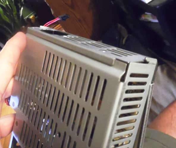
Open PSU
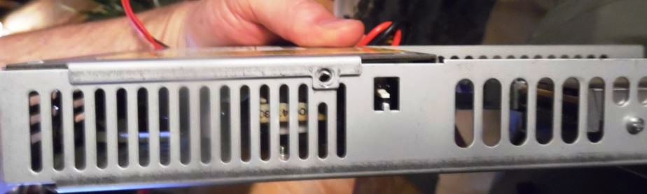
Remove sheet metal screw on inner side with small Phillips. Note the two pin
port? My guess is a Wake-On-LAN...
Remove small sheet metal screw on outer side. Note that there is a rivet
holding the top side to the outer side, right next to the power connectors.
Drill the rivet out.
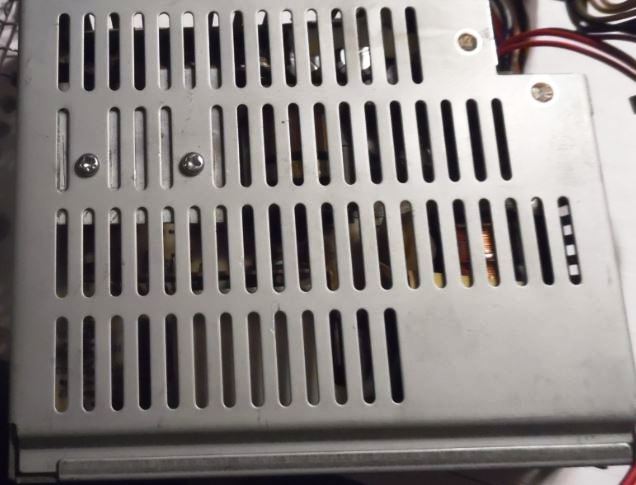
Remove the two small phillips screws that thread into a heatsink.
Note: If you leave these two screws in, the PSU
will not open. The PSU PCB is actually fastened to the top cover!
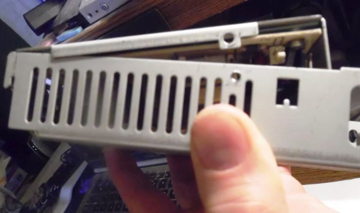
Now pivot top on rear lip.
The top cover hooks over a lip on the rear of the PSU case. You do NOT have
to unscrew the AC socket!
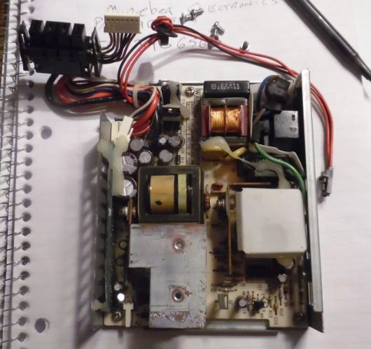
Top view of opened PSU. Note the inverted "L" shaped heatsink, with the two
threaded mounting holes?
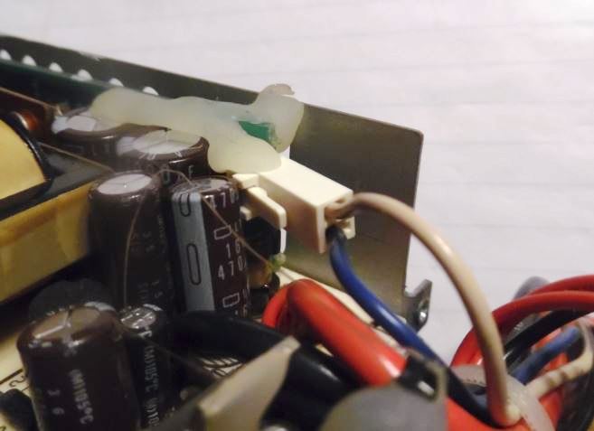
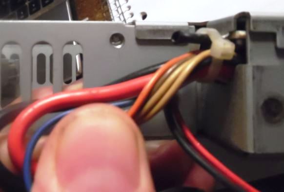
There is a small PCB mounted at the front of the case. It provides the -12 V
DC. Blue lead, -12 V DC, cream lead is -12 V Ground.
Close PSU
Pretty much in reverse.
Hook the rear wall of the PSU over the lip on the bottom. Rotate the top
cover down until it seats on the frame in front. Start the threaded heatsink
screws on the bottom of the PSU first. Now you can adjust the top of the case a
little so you can start the metal screws.
Once all 4 screws have been started and slightly snugged, tighten the
heatsink screws, then the top cover metal screws. Done.
The two threaded screws are used to attach the bottom of the PSU case to a
heatsink. Two positives: first, the PSU will be more rigid, second, the frame
is now thermally bonded to the heatsink. In effect, making the case part of the
heatsink.
|