|
The First Micro Channel Product
AT/MCA Compatibility
Backplane Connectors
Backplane Modifications
7552 Card in Model 60?
Programmable Option Select
BIOS Origins
The vast majority of the information presented here comes from the following source:
"Surface Computer System Architecture for the Advanced Unmanned Search System (AUSS)"
Technical Report 1538, Dec 1992, unclassified NCCOSC document - PDF, alternative PDF.
The First Micro Channel Product
The 7552 Industrial Computer was the first Micro Channel product on the
market. IBM's Manufacturing Systems Products (MSP) group supposedly not only
announced but began shipping the machine six months before the Personal
System/2 announcement.
7552 Industrial Computer - announced 07 Oct 1986, planned *general* avail. Mar 1987
PS/2 Models 50 & 60 - announced 02 Apr 1987, planned avail. Apr 1987
IBM spokesman Jim Monihan said:
The Micro Channel bus architecture is the same as that used in
Models 50 and 60 of the PS/2 systems, but will not have a major role in current
applications on the 7552. IBM still uses adaptors to accommodate all AT cards
on the industrial computer and characterizes the Micro Channel bus as
"providing for the future."
The 7552 was also offered by other companies:
- Gould's Industrial Automation Systems division - "FM 1100"
- Rockwell International Corp. subsidiary Allen-Bradley - "6122"
Sources:
186-185 IBM 7552 Industrial Computer
187-049 IBM Personal System/2 Model 50 (8550-021)
187-050 IBM Personal System/2 Model 60 (8560-041 & -071)
Electronic Business, 15 Nov 1987 (page 126)
AT/MCA Compatibility (from NCCOSC)
In theory, the 7552 PCs were supposed to be "AT compatible". After receiving
our first unit, we discovered that the machines were in fact only partially
compatible. The bus design turned out to be a hybrid of the AT Industry
Standard Architecture (ISA) design and the new PS/2 Micro Channel (MCA) design.
The biggest compatibility problem with the ISA specifications was that some
signals were left off the bus. In addition, certain details, such as the
address location of the keyboard port, were changed in such a manner that the
7552 was incompatible with some operating system software. These
incompatibilities are covered in detail in appendix A, which discusses bus
modifications. After the initial evaluation of the first 7552 was completed, it
was decided to remove the 10 MHz 80286 CPU and memory cards and replace them
with third-party 3 20 MHz 80386 CPU/memory cards. The net result gave us ISA
bus compatibility and software compatibility with our desktop machines, plus a
significantly higher processing speed. The 7552 enclosure, passive backplane,
power supply, and card shrouds and adapters have been kept and have proven to
be reliable and trouble free.
Backplane Connectors
The IBM 7552 industrial computer uses a passive backplane design. Feature
cards plug into the bus via two 96-pin (3 x 32) DIN connectors. The signals
assigned to the backplane bus are composed of signals from three sources:
- IBM Micro Channel (16-bit)
- IBM PC AT bus subset
- IBM 7552 unique signals
Ed. Tom: The IBM 7552 backplane features 9 card
positions, One of which is typically unusable because the DASD module physically
occupies two slot positions but uses only one pair of backplane connections.
Feature Adapter/Backplane Connectors
System Bus Backplane Connector J01-J09
| Pin | Signal Name | Pin | Signal Name | Pin | Signal Name |
|---|
| C32 | GND | B32 | CHRDY ADP (1) | A32 | GND |
| C31 | DC PWR GOOD | B31 | DRQ7 (1) | A31 | BKUP DISC |
| C30 | +5 VDC | B30 | -DACK7 (1) | A30 | -DO 1 |
| C29 | -PR PWR CK | B29 | DRQ6 (1) | A29 | -IRQ8 |
| C28 | +12 VDC | B28 | -DACK6 (1) | A28 | -IRQ1 |
| C27 | -TEMP CK | B27 | DRQ5 (1) | A27 | -IRQ15 |
| C26 | -12 VDC | B26 | -DACK5 (1) | A26 | -IRQ14 |
| C25 | -P/S CK | B25 | -XMEM W (1) | A25 | -IRQ12 |
| C24 | +5 VDC | B24 | DRQ0 (1) | A24 | -IRQ11 |
| C23 | Reserved | B23 | -XMEM R (1) | A23 | -IRQ10 |
| C22 | GND | B22 | -DACK0 (1) | A22 | GND |
| C21 | -CD DS 16 | B21 | IRQ15 (1) | A21 | DPAR 1 |
| C20 | Reserved | B20 | IRQ12 (1) | A20 | D15 |
| C19 | -SBHE | B19 | IRQ11 (1) | A19 | D14 |
| C18 | -REFRESH | B18 | IRQ10 (1) | A18 | D13 |
| C17 | -DS 16 RTN | B17 | -IO CS16 (1) | A17 | D12 |
| C16 | -SFDBK RTN | B16 | -MEM CS16 (1) | A16 | D11 |
| C15 | Reserved | B15 | -BHE (1) | A15 | D10 |
| C14 | CHRESET | B14 | LA0 (1) | A14 | D9 |
| C13 | GND | B13 | LA1 (1) | A13 | D8 |
| C12 | CD CHRDY | B12 | LA2 (1) | A12 | D7 |
| C11 | GND | B11 | BALE (1) | A11 | GND |
| C10 | -CD SFDBK | B10 | LA3 (1) | A10 | D6 |
| C09 | +5 VDC | B09 | T/C (1) | A09 | D5 |
| C08 | CHRDYRTN | B08 | LA4 (1) | A08 | D4 |
| C07 | +5 VDC CONT | B07 | LA5 (1) | A07 | D3 |
| C06 | M/-IO | B06 | IRQ3 (1) | A06 | D2 |
| C05 | +12 VDC | B05 | LA6 (1) | A05 | D1 |
| C04 | -CMD | B04 | IRQ4 (1) | A04 | D0 |
| C03 | +5 VDC | B03 | LA7 (1) | A03 | DPAR 0 |
| C02 | -CHK | B02 | IRQ5 (1) | A02 | -DPAR EN |
| C01 | GND | B01 | LA8 (1) | A01 | GND |
System Bus Backplane Connector J10-J18
| Pin | Signal Name | Pin | Signal Name | Pin | Signal Name |
|---|
| F32 | GND | E32 | LA9 (1) | D32 | GND |
| F31 | -TC | E31 | LA10 (1) | D31 | -S1 |
| F30 | +5 VDC | E30 | IRQ7 (1) | D30 | -S0 |
| F29 | ARB/-GNT | E29 | CLK (1) | D29 | A0 |
| F28 | +12 VDC | E28 | LA11 (1) | D28 | A1 |
| F27 | ARB3 | E27 | LA12 (1) | D27 | A2 |
| F26 | -12 VDC | E26 | DRQ1 (1) | D26 | A3 |
| F25 | ARB2 | E25 | LA13 (1) | D25 | A4 |
| F24 | +5 VDC | E24 | -DACK1 (1) | D24 | A5 |
| F23 | ARB1 | E23 | LA14 (1) | D23 | A6 |
| F22 | GND | E22 | DRQ3 (1) | D22 | GND |
| F21 | ARB0 | E21 | LA15 (1) | D21 | A7 |
| F20 | Reserved | E20 | -DACK3 (1) | D20 | A8 |
| F19 | -IRQ7 | E19 | LA16 (1) | D19 | A9 |
| F18 | -IRQ6 | E18 | -IOR (1) | D18 | A10 |
| F17 | -IRQ5 | E17 | LA17 (1) | D17 | A11 |
| F16 | -IRQ4 | E16 | -IOW (1) | D16 | A12 |
| F15 | -IRQ3 | E15 | LA18 (1) | D15 | A13 |
| F14 | -IRQ9 | E14 | -SMEM R (1) | D14 | A14 |
| F13 | GND | E13 | LA19 (1) | D13 | A15 |
| F12 | -BURST | E12 | -SMEM W (1) | D12 | A16 |
| F11 | GND | E11 | AEN (1) | D11 | GND |
| F10 | -PREEMPT | E10 | IRQ9 (1) | D10 | A17 |
| F09 | +5 VDC | E09 | -SETUP 1 (1) | D09 | A18 |
| F08 | -ADL(ALE) | E08 | -SETUP 2 (1) | D08 | A19 |
| F07 | -5 VDC | E07 | -SETUP 3 (1) | D07 | A20 |
| F06 | MADE 24 | E06 | -SETUP 4 (1) | D06 | A21 |
| F05 | +12 VDC | E05 | -SETUP 5 (1) | D05 | A22 |
| F04 | -CD SETUP | E04 | -SETUP 6 (1) | D04 | A23 |
| F03 | +5 VDC | E03 | -SETUP 7 (1) | D03 | AUDIO GND |
| F02 | OSC | E02 | -SETUP 8 (1) | D02 | GND |
| F01 | GND | E01 | -SETUP 9 (1) | D01 | GND |
Notes:
(1) IBM PC AT Unique Signals
Backplane Modifications (from NCCOSC)
To work around software and hardware incompatibilities, the standard IBM
7552 bus was modified to make it capable of being 100 percent compatible with
the full IBM PC AT Bus standard. To accomplish this, modifications were made to
the IBM PC feature adapter. A side view of the adapter is shown below in figure
A-1. This adapter accepts a standard IBM PC AT accessory card and then maps its
bus signals to lines on the 7552 bus. A standard AT card mates to a 98-line bus
via a 62-pin and a 36-pin edge card connector. The feature adapter has the
appropriate mating edge connectors on one side into which the AT card is
inserted. On the other end of the feature adapter are two 96-pin DIN connectors
that mate to the 7552 backplane. In between, traces are etched that map AT bus
signals to 7552 bus signals. For whatever reason, IBM chose not to support all
the AT bus signals on the 7552 bus. The signals left off were:
- DMA level 2 (DRQ2 and -DACK2)
- Interrupt levels 6 and 14 (IRQ6 and IRQ14)
- AT adapter cards that are bus masters (use the -MASTER line)
- Zero wait state bus cycles
To reinstate these signals and achieve sufficient compatibility to the IBM
PC AT standard for our hardware and application software, the original 7552 CPU
and memory cards were removed and replaced with third-party CPU/memory cards
designed for operating in AT-compatible passive backplanes. The standard 7552
CPU cards incorporated changes that used some AT signals and some Micro Channel
signals. This hybrid architecture created hardware and software
incompatibilities with our surface computer designs, necessitating replacement
of the 7552 CPU and memory cards. Once replaced, the 7552 bus was made
compatible with the AT standard by adding the necessary missing signals back
onto the bus via changes to the feature adapter signal mappings. The bus signal
definitions as delivered for the 7552 are shown above.
7552 Card in Model 60? (by Major Tom)
In the "Bus Wars" episode
of Computer Chronicles Chet Heath showed a modified Model 60 with a special
processor board to demonstrate the possibility and benefits of multiple
processors on the Micro Channel bus.


A modified Model 60 with the "test tool" processor board installed
Compare the form-factor of this test card to the 7552 Processor Board
(pictured below). They seem to be approximately the same size and the backplane
connectors appear to be located in the same area. Even the position of the PCB
mounting holes is a close match...
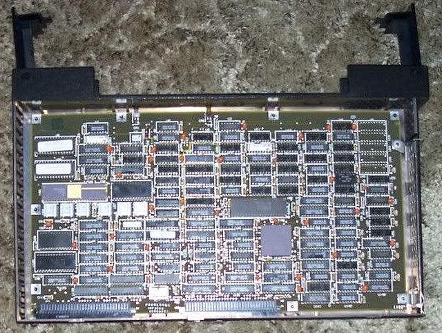
7552 Processor Board
In the video, Chet says:
"This is a Model 60 with the test tool built by Ernie Mandese at Boca Raton...
that was built in 1986 to demonstrate – to our satisfaction – that
the Micro Channel could support a number of processors."
Hmm, has the 7552 design started its life as a development/test platform for
the Micro Channel Architecture?
Programmable Option Select (by Major Tom)
The POS functionality known from the other x86-based MCA systems is
implemented somewhat differently here. There are 9 device positions in total
(compared to the usual 8 or less) - one of which is used by the CPU card. The
last (rightmost) position is typically unused as the connector is physically
blocked by the two-slot-wide DASD module. Similar to the standard MCA the 7552
uses 2-byte adapter IDs to identify the individual cards (this possibly applies
to the CPU card as well). The "Setup" option of the Diagnostic Diskette can be
used to view the installed adapters/devices:
 IBM 7552 "Setup" Device List (all slots empty, incompatible system used)
The system doesn't use the standard ADF files known from the PS/2 world.
The supported device IDs and description/configuration data are likely all
"hardcoded".
When Int 15h
Func. C0h is called on the 7552, the machine identifies itself as a
Dual-Bus System and reports the presence of the Micro Channel bus. It supports
the standard Int 15h Func. C4h - "Programmable Option Select" call as well
(incl. subfunctions 00h, 01h, and 02h). The base POS register address is 100h
as in the case of the standard PS/2s. The 7552 uses a non-standard port E1h to
enable/disable setup mode for one of the 9 devices (PS/2s use port 96h for
adapter setup and 94h for planar setup).
Why does the 7552 use a unique MCA/POS implementation and why IBM never
widely marketed the feature? Maybe they modified it to separate the industrial
implementation from the consumer PS/2 world? Or perhaps what we see here is an
*earlier* Micro Channel iteration that started as a development platform, and
IBM later decided to market it? We can only speculate...
The later 7568 "Gearbox 800" shares the
same form-factor with the 7552 but the underlying MCA/POS implementation is
compatible with the PS/2 world.
BIOS Origins (by Major Tom)
The 7552 system BIOS is rather unusual as well. Unlike all the other
x86-based MCA machines, the 7552 has a single-segment BIOS - 64 KB. One half of
this space is consumed by the 32 KB ROM BASIC. And the BIOS code itself is much
closer to the IBM AT codebase, than to the earliest known PS/2 firmware -
the Model 50/60 ROM revision 0. It also completely lacks the ABIOS code...
|