|
Control Panel Connector Variants
Control Panel Connector Pinout
8-pin Cable on 12-pin Header
12-pin Cable on 8-pin Header
Control Panel Connector Variants
The 8540 systems used a "Control Panel" with an 8-pin "Control Panel" header
on the system board for the power switch, power/HD LEDs, and PC speaker:
- Control assembly w/o volume control - 92F0002 (Power switch, Cable, Speaker)
The 95xx Premium systems used a 12-pin "Control Panel" header that adds a
symmetrical +/-12 V supply for the power audio amp used by the speakers. The
"Ultimedia Control Panel" had a speaker jack,
microphone jack, volume knob, and a power audio amp for external speakers:
The following planars feature the compatible 8-pin or 12-pin Control Panel
header:
Control Panel Connector Pinout
Pinout information provided by Daniel Hamilton.
The pin arrangement on the 8-pin header forms the center of the 12-pin
headers. This allowed IBM to continue using the existing "Control Panels" on
both 8-pin and 12-pin "Control Panel" headers.
| 85xx Models |
95xx Models |
 |
|
| Pin |
Description |
Pin |
Description |
| 1 |
PWR LED - |
2 |
PWR LED + |
| 3 |
HD LED + |
4 |
PWR Sense + |
| 5 |
HD LED - |
6 |
PWR Sense - |
| 7 |
Audio - |
8 |
Audio + |
|
| Pin |
Description |
Pin |
Description |
| 1 |
N/C |
2 |
N/C |
| 3 |
PWR LED - |
4 |
PWR LED + |
| 5 |
HD LED + |
6 |
PWR Sense + |
| 7 |
HD LED - |
8 |
PWR Sense - |
| 9 |
Audio - |
10 |
Audio + |
| 11 |
-12 V (Amp) |
12 |
+12 V (Amp) |
|
Note: Both views are at the face of the plug or
socket. So, the oddity of the numbers being "flipped" top to bottom is correct.
Think of plugging the plug into the socket, now the pins match.
Warning: Pay attention to the pin numbering (the
pins were previously marked in a non-standard order). Incorrect cable wiring
may lead to damage! Dan Hamilton blew one of the LM386 amp ICs on his Ultimedia
module by mis-wiring the cable following the misleading (now corrected)
numbering scheme.
8-pin Cable on 12-pin Header
Why a 12-pin connector? Not all 9557/9577 were Ultimedia, so
it was cheaper to use a 12 pin header for both 8 pin [2x4]
and 12 pin [2x6] cables. Can't do that with a 10 pin [2x5]
header, odd number of columns, the older 8 pin cables would
not fit (key would be offset).
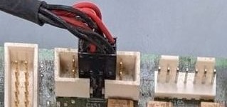
12-pin Cable on 8-pin Header
It's possible to use the 12-pin Ultimedia Panel connector with a 8-pin
planar header. See HERE for more
information.
|