|
Auxiliary Video Extension Pinout
Auxiliary Video Extension Signal Descriptions
Auxiliary Video Connector
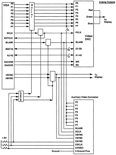
Auxiliary Video Block Diagram
Related Registers
Source: PS/2
Hardware Interface Technical Reference May 1988 (Pages 487-490 physical)
Auxiliary Video Connector (AVE)
The auxiliary video connector is a 20-pin connector located in-line with one
of the channel connectors on the system board. (Ed.
The 8580-Axx planar and many older
PS/55 planars have *two* AVE slots.) This connector allows
video data to be passed to and from an adapter. The video buffers can be turned
off, and video output from the adapter can be sent through the video DAC to the
display connector. The full channel is available for use by the adapter. Video
output can be passed in only one direction at a time. The 'dot clock' signal
cannot drive both EXTCLK to the VGA and PCLK to the DAC.
Auxiliary Video Block Diagram

Related Registers
Miscellaneous Output Register - Hex 03CC/03C2 (Page 432 physical)
Bits 3, 2: These two bits select the clock source. The external clock is
driven through the auxiliary video extension. The input clock should be kept
between 14.3 MHz and 28.4 MHz.
| Bits | Function |
|---|
| 3 | 2 |
|---|
| 0 | 0 | Selects 25.175 MHz clock for 640/320 Horizontal PELs |
| 0 | 1 | Selects 28.322 MHz clock for 720/360 Horizontal PELs |
| 1 | 0 | Selects External Clock |
| 1 | 1 | Reserved |
|