|
MC 32 Electronic Extender Datasheet
MC32EE User's Guide (2 pages/sheet) (thx to David Beem)
AZ-COM Product Brochure (thx to David Beem)
AZ-COM Website (archived)
EE Software Control (Status Register and Control Registers)
General Description
Specifications
Universal MC Extender 32
Overcurrent Sensing Circuitry
Base Address Selection
Note: No ADF, this is just an extender card. The
on-board control registers and parallel I/O are unknown/invisible to the System
Configuration utility!
General Description
The Universal MC Extender 32 (UME32) is a device designed to enhance the
process of testing and developing Micro Channel Bus products. With the UME32,
you can disconnect the power and bus signals from the top connector and safely
insert or remove tested cards with the PC power turned on. This not only saves
time, but also protects the components of the PC from damage that results from
constant Power On - Power Off cycling.
Overcurrent Sensing Circuitry that detects excessive current
consumption and protects PC power lines by automatically disconnecting the
tested card if overcurrent is detected. You can change the sensing threshold
by simply changing jumper settings or the current sensing resistors.
Simple to use optional software interface capabilities with 7 I/O
addresses available. Free POS register initialization program is included. The
demo program can be downloaded from our FTP Page (see menu bar below).
Four LED's, one indicates whether the power to the top connector is
on or off, the other three indicate an overcurrent condition and help detect
faulty cards. An overcurrent condition can also be tested by reading the status
register.
Bus switches installed in sockets for easy replacement if damaged by
faulty tested cards.
Breadboard area with all crucial signals available on the board.
Ability to connect external power to the top connector to test cards
under various power supply voltages.
Specifications
Physical Traits: Size - 4.6" (h) x 12.3" (l), Weight - 10.0 oz.
Maximum Current: +5V is 4A. All others are 2A.
Overcurrent Settings: Factory settings - 4A on +5V, 0.5A on +12V,
and 0.5A on -12V.
LED Indicators: Power On (1) and Overcurrent (3).
Bus Switches: 7 Ohm maximum, 10pF maximum at 0V/25 C.
Signal's Direction: All signals except for the RESET signal are
connected to the PC Bus via a bi-directional analog switch. The RESET signal is
uni-directional from the PC Bus into the top connector.
Universal MC Extender 32 "UME32" aka "MC32EE", P/N 9900-15-10
![[P]](/other/img/photo.gif "Front") (thx to David Beem)
(thx to David Beem)

A2 MCA test pads
B1 Pads for 4-pin header
B2 Pads for 8-bit Port
GND Ground test point
JP1-3 Base Address
JP5 +12 V Ext Power
JP6 Bus Disable
JP7 -12 V Ext. power
JP8 +12 V O/C threshold
JP9 +5 V O/C threshold
JP10 +5 V O/C threshold
JP11 +5 V O/C threshold
JP12 -12 V O/C threshold
JP13 Unknown
JP14 +5 V Ext. Power
LED1 +12 V O/C indicator
|
LED2 +5 V O/C indicator
LED3 -12 V O/C indicator
LED4 Power to top connector
P1 MCA card edge
P2 Top MCA connector (for DUT)
Q5-7 power transistor? (power switch)
S1 Main switch
U1-13 PI5C3384AP bus switches
U14,16 TIBPAL16L8-25CN PAL
U15 TIBPAL16R4-25CN PAL
U17 74LS373
U18 74LS259
U19,20 Unknown
U21,22 74HCT74
U25 7805 5 V reg. (breadboard)
|
Status LEDs for Top Connector
The MC32EE automatically disconnects power and bus signals upon overcurrent.
Upon overcurrent, the corresponding LED is turned on, and stays on, until the
power to the top connector is turned off.
Warning! Do NOT insert or remove card if Power LED
(LED4) is lit!
S1 Main Switch
Controls the power to the top connector. Switch it on and power is applied
to top connector together with RESET signal (HIGH). @ 60 ms later, the bus
signals are connected, and the RESET signal to tested card follows the state of
the RESET signal on MC bus. Jumpering JP6 will disable connection of bus
signals. When you turn power to top connector OFF, the reverse sequence takes
place: first the bus is disconnected, then approximately 60 ms later the power
is disconnected.
Power MOSFETs connect/disconnect power to the Device Under Test (DUT).
External Power Supply
An external power supply can be connected to the tested card without using
the PSU from your PC. To connect an external power supply, make cuts in the
traces (on the solder side) corresponding to the power lines as marked on the
reverse side of JP5, 7, and 14. The external power supply needs to be connected
into the left side of the corresponding jumper.
JP6 - Bus Disable
OFF - Bus enabled. All bus signals disconnected from top connector.
ON - Bus disabled. Bus signals connected to top edge connector if power
is enabled. IRQ lines and DATA lines can be individually disabled by JP5 and
JP6.
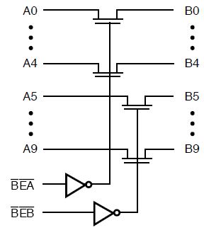
CMOS Bus Switch
CMOS Bus switches isolate bus signals. Socketed for easy replacement. Each
3384 has ten switches, five switches in two banks.
 |
 |
| 3384 Functional Block Diagram |
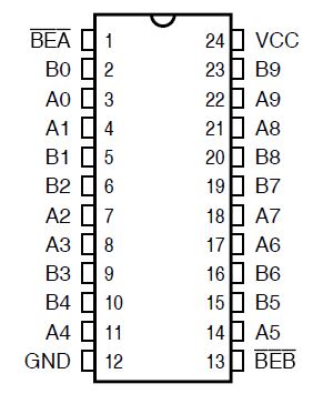
3384 Pin Configuration |
-BEA/-BEB - Bus Enable inputs
Pericom PI5C3384 10-bit, 2-port bus switch
Quality Semiconductor QS53348 (QSI was bought by IDT @ 1997-ish).
B1 Connector
Just right of the current limiting jumpers are pads for a 4-pin header
marked as B1.
B2 Connector - 8-Bit Port
The small breadboard area (8x27, top row +5 V, bottom row ground) makes it
easy to add peripherals to your test circuitry. All signals required to
implement a parallel I/O port are conveniently located at the B2 connector.
| Pin | Name | Description |
|---|
| 1-8 | D0-D7 | Unbuffered data lines from the MC Bus. |
| 9 | WSEL | Active low I/O write line. Decoded by UME32 and activated when I/O write to address equal BASE ADDRESS +1 (example 801 HEX) is executed on the MC Bus. |
| 10 | RSEL | Active low I/O read line. Decoded by UME32 and activated when I/O read from address equal BASE ADDRESS +1 is executed on the MC Bus. |
| 11,12 | GND | Ground from the MC Bus. |
| 13 | -12 V | -12 V power supply from the MC Bus. |
| 14 | +12 V | +12 V power supply from the MC Bus. |
| 15 | +5 V | +5 V power supply from the MC Bus. |
Note: This is not an LPT port, just a generic
8-bit parallel I/O port that can be used for testing or to implement some
additional functionality — either on the provided breadboard area or
externally.
Overcurrent Sensing Circuitry
Overcurrent detection works by sensing a voltage drop across the resistors
in series with the power supply lines. When the voltage drop exceeds the limit
(listed below), the hardware on the UME32 disconnects the power and bus signals
from the top connector. The appropriate bit in the status register is cleared
and the corresponding LED indicator is turned on. Overcurrent status is cleared
by using SW1 to turn the power to the top connector OFF.
External power supply can be connected while maintaining overcurrent
sensing.
Overcurrent Sensing Levels
+5 V activates at 100 mV drop across R13. Factory set to 4 A.
+12 V activates at 250 mV drop across R15. Factory set to 0.5 A.
-12 V activates at 250 mV drop across R16. Factory set to 0.5 A.
Lower overcurrent sensing threshold by removing JP8 through JP12.
Overcurrent Sensing Jumpers
| Jumper |
Vdc |
Threshold |
Result |
Default |
| J8 |
+12 V |
1/4 |
0.25 A |
0.50 A |
| J9 |
+5 V |
1/8 |
0.50 A |
4.00 A |
| J10 |
+5 V |
1/4 |
0.25 A |
| J11 |
+5 V |
1/2 |
2.00 A |
| J12 |
-12 V |
1/2 |
0.25 A |
0.50 A |
Example: Removing JP11 will lower the sensing threshold for +5 V by
a factor of 1/2, i.e., from 4 A to 2 A. Removing JP10 would further lower the
threshold by 1/4 of the original value, i.e. 2 A to 1 A.
Note: the Amperage in the "Result" is the
resulting amperage after removing the Overcurrent Sensing Jumpers. It might be
that the +5 V is reduced by removing J11, J10, and J9 in sequence, e.g. they
shouldn't be removed out of order. I have no idea... YMMV. "Default" is the
factory set limit with the jumper(s) for that voltage installed. -LFO
Base Address Selection
To avoid conflict with other devices installed in the Computer (including
the test card), the selected I/O address should be different from the address
of any other device on the MC Bus. Control and status registers occupy one I/O
location equal to the base address. Breadboard area -WR and -RD are activated
when the I/O address equal to the BASE ADDRESS + 1 is selected.
| JP1 |
JP2 |
JP3 |
Base Addr. |
| ON |
ON |
ON |
800h |
| ON |
ON |
OFF |
1000h |
| ON |
OFF |
ON |
1800h |
| ON |
OFF |
OFF |
2000h |
| OFF |
ON |
ON |
2800h |
| OFF |
ON |
OFF |
3000h |
| OFF |
OFF |
ON |
3800h |
|