|
Additional Hard-drive Power Connector
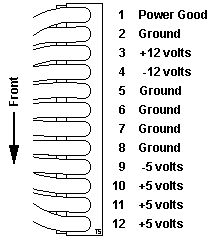
J7 Connector Pinout Models 25, 25SX and 25-286
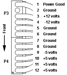
P3 / P4 Connector Pinout Model 30 and 30-286
Power Good
J7 Connector Pinout Models 25, 25SX and 25-286
(Pin 1 to rear of system)

|
| -Lead Pin |
+Lead Pin |
V dc Min |
V dc Max |
| P7-5 |
P7-10 |
+ 4.8 |
+ 5.2 |
| P7-9 |
P7-5 |
+ 4.5 |
+ 5.4 |
| P7-5 |
P7-3 |
+11.5 |
+12.6 |
| P7-4 |
P7-8 |
+10.8 |
+12.9 |
|
P3 / P4 Connector Pinout Model 30 and 30-286
(Pin 1 to rear of system)

|
| -Lead Pin |
+Lead Pin |
V dc Min |
V dc Max |
| P3-5 |
P4-4 |
+ 4.8 |
+ 5.2 |
| P4-3 |
P3-6 |
+ 4.6 |
+ 5.5 |
| P4-1 |
P3-3 |
+11.5 |
+12.6 |
| P3-4 |
P4-2 |
+10.8 |
+13.2 |
|
The manually-switchable power supply must be switched to either the 100-125
Vac or the 200-240 Vac range before the power cord is plugged into an outlet.
The ac input is converted to dc outputs that supply the system with the proper
operating voltages.
When the system is powered-off for five seconds or more and then powered-on,
the power supply generates a 'power good' signal that resets system logic. The
presence of the 'power good' signal indicates that the power supply is
operating properly and that the minimum under-voltage sense levels have been
established. This means that all system-board power requirements have been
met.
Output
(Vdc) |
Minimum Under-Voltage
Sense Level (Vdc) |
| + 5.0 |
+ 4.5 |
| - 5.0 |
- 4.3 |
| +12.0 |
+10.8 |
| -12.0 |
-10.2 |
Once the minimum under-voltage sense levels are established and the 'power
good' signal has risen to its active level, all system board power requirements
have been met and the power-on self-test begins.
Power Good
Power Good should read +3.5 to +5 V when system is operating correctly. If
it is not, remove all adapters, cables, and extra memory then try again. If
power good is now valid, a device was causing a short. Install adapters one at
a time and retest. The bad device will prevent power good from coming up.
|