|
@6042.ADF EtherLink/MC Ethernet Adapter
3C523X.EXE V3.3 EtherDisk for ELMC/TP (8193-04)
3C523N.EXE EtherDisk, 3C523 family w/latest patches, V3.4.
LANscope.rar LAN Datascope For Ethernet
3c523 Technical Reference (Mar 1991)
3c523 Technical Reference (Jan 1989)
3C523 Etherlink/MC
3C523 Etherlink/MC TP
Setting Jumpers on EtherLink/MC TP Adapter
Late 3C523 Etherlink/MC
Older Versions not Compatible with 486+
LAN Datascope For Ethernet
3C523 ADF Sections
3C523 Etherlink/MC
![[P]](/other/img/photo.gif "Front")
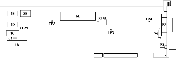
1A RPL socket
1C MAC address ROM
1D,1E 8Kx8 SRAM
2E 12 MHz osc
6E P82586-6 Eth LAN co-pro
J1 System config jumper
|
LP1 Neon Lamp
P2 AUI port
P3 BNC port
TP1-4 test point pin
XTAL 20.00 MHz xtal
|
1D,1E
Logic L7C185VC85,
Atmel AT3864-12RC or compatible
8Kx8 SRAM.
J1 System Configuration Jumper
J1 allows the adapter to be enabled even though the host system's
Configuration RAM contains no entry for it. The only time J1 should be moved
from "A" to "B" is if the adapter has been installed in a computer that has no
floppy disk drives and there as no provision for temporarily installing one to
run the configuration utility on the system's reference diskette.
When the jumper is installed in position "B", the Card Enable feature of POS
is overridden so that the adapter's Start ROM program can be accessed during
the ROM scan that occurs during the power-up sequence. This Card Enable
override is necessary when the host system's configuration RAM doesn't contain
an entry for the adapter. Without the jumper, if there isn't an entry in the
system's CMOS RAM for the adapter, the system will leave the adapter in the
disabled state and its ROM won't be found during the ROM scan.
When using the adapter in this specialized configuration, care must be taken
that no bus conflicts will occur because the adapter will be enabled before it
is configured. The power-up default configuration for the adapter is as
follows: I/O base address = 0300H, memory base address =0C0000H, interrupt
level = 12 and the on-board transceiver will be selected. For general
operation, the jumper should be in position "A".
3C523 Etherlink/MC TP
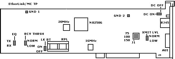
Setting Jumpers on EtherLink/MC TP Adapter
Impedance
- Use a test device to verify the impedance of your cable from wiring closet
to station.
- Choose setting closest to that characteristic impedance.
Default Setting: 100 ohms
Alternative Settings: 75 ohms, 150 ohms
Receive Threshold, Link Beat, Equalization, Transmit
Level, and DC Signal
Jumper Settings for 10BASE-T and Non-10BASE-T Hubs (?)
|
10BASE-T
(default) |
SynOptics
LattisNet
(non-10B-T) |
HP StarLAN 10,
AT&T StarLAN 10,
DAVID Systems
(non-10B-T) |
BULL Hub 10
(non-10B-T) |
| Link Beat | ON | OFF | OFF | OFF |
| Equalization | TX | RX | TX | RX |
| DC Signal | OFF | ON | OFF | OFF |
| Xsmit Level | NORM | LOW | NORM | LOW |
| Rcv Thres | NORM | LOW | NORM | LOW- |
Late 3C523 Etherlink/MC
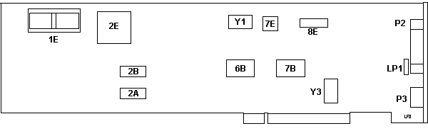
1E RPL socket
2A,2B CXK5864BM-10L
2E N82586 Eth LAN co-pro
6B,7B 3Com 6408-01
7E NS DP8391AV
8E Motorola MC10116L
|
LP1 Neon Lamp
P2 AUI port
P3 BNC port
Y1 20.00000 MHz osc
Y3 16 MHz osc
|
I found two of these in a 3172 Interconnect Controller. Marked "(C) 1990
3Com" on the front.
Older Versions not Compatible with 486+
The "old" 3C523 have a copyright date of 1987 on them and will only work
properly in a 286 or 386. From my experiences, it will only let the first 8MB
RAM be usable no matter how much RAM you have installed. The newer revision
will have a 1990 or 1991 date on it.
From Peter:
Fact is: some series of the older Ethernet/MC have a microcode
incompatible with 486-processors. (Bus signaling most likely - haven't tested
that in depth)
Symptom: they worked fine as long as they were used in Mod. 70/80 - but when
the customer swapped them to the new bought 76/77 they went belly up and did
not even pass the DOS-based diags test.
These are older ones produced before 1990 - but ironically not all old cards
are automatically affected. There was a diagnostic program available from 3COM
(I think it came with the revised E/MC) which checks the microcode level and
warns for possible incompatibilities. In addition some of the setup / diags and
driver software had a problem with later OS-versions (did not run properly
under PC-DOS 4.x and above due to "version conflict"). Whatever.
Component Differences, Old vs. New
>Is that a 3C523? ISTR that those (or most of them, anyway) wouldn't work
properly in anything than a 386.
The original 3C-523 has a limitation - the later ones (3C-523B) hasn't.
Roughly the two can be differed by looking on the board:
Old Model
Round "transformer", many "through-hole" chips and "classical" resistors,
long DIL "i" (Intel) 82586 MCU, "(C) 1987 3Com" at frontside.
New Model
Square "3Com" transformer, mainly SMD chips with square QFP "i" Intel 82586
MCU, "(C) 1991 3Com" along the bottom/front.
The old one will most likely not run with anything bigger than a 386DX - the
new one hasn't got this problem. Works with 486 and Pentium. Both cards have
the same card-ID and use the same ADF, so you cannot tell which is which by the
ID only.
LAN Datascope for Ethernet
This Program was authored by Keith Shortt in IBM Toronto as a LAN
Development Tool and is being distributed as an interim tool for problem
determination on Ethernet Local Area Networks. It supports only the 3COM PS/2
ETHERNET Adapter #3C523 available from 3COM distributors and runs under DOS 3.1
or higher.
The 3COM adapter is also known as the ETHERLINK/MC Adapter and includes the
Micro Channel adapter and a diskette containing diagnostics, the adapter
description file for configuring the PS/2, and a software driver which is not
needed with this program. Note that this adapter provides both on-board
transceiver and external transceiver connections.
The Datascope program and adapter operate on PS/2 Micro Channel systems
including the IBM P70. Follow the instructions included with the 3COM adapter
to install the adapter, configure the PS/2, and test the adapter. The 3+ driver
is not needed for this application.
The two files included with this package are SCOPE_EN EXEBIN and SCOPE_EN
HLP which provide the program and documentation to trace and display traffic on
an Ethernet LAN. Note that an adapter is not required to display and interpret
trace files previously taken. SCOPE_EN EXEBIN should be downloaded in binary
form.
AdapterId 6042 3Com EtherLink/MC Ethernet Adapter
Enable/Disable Adapter
Disabled if you are not using adapter and
enabling it causes a conflict with another device.
<"
Adapter Enabled >, Adapter Disabled
I/O Address Range
Addresses used by EtherLink/MC. Addresses
cannot be used by another installed device
<"
300 to 307 ">, 1300 to 1307, 2300 to
2307, 3300 to 3307
Interrupt Level
Interrupt level used by EtherLink/MC. This
can be shared, but you may be able to improve
performance by selecting a level that is not used by any
other device.
<" Channel 3 " (
INT 3)>, 7, 9, 12
Packet Buffer RAM Address
Range
RAM and ROM addresses used by
EtherLink/MC. These cannot be used by any other
installed device. Each range is 16K bytes of RAM
followed by 8K bytes of ROM
<" 0C0000 to
0C5FFF " >, 0D0000 to 0D5FFF , 0D8000 to
0DDFFF
Transceiver Type
On-Board used for BNC or RJ45 (EL/MC
TP only). External used with AUI.
<" On-Board (BNC
or RJ45) ">, External (AUI)
Diagnostics Warnings
The computer containing the EtherLink/MC adapter to be tested must be
running DOS. If this computer is an operating server, notify all users of the
server to save their work and log out from the network. The diagnostic program
disrupts the normal operation of the server, and work that is not saved may be
lost. The diagnostic tests do not function properly if you run them after
booting your system with NetBIOS installed. Please start your computer with a
standard boot diskette that does not contain a network driver.
Note: If Group 3 tests are running while computer
is connected to an active network, intermittent packet exchange failures may
occur before the tests are done. These failures can be avoided by running Group
3 tests on an inactive network in which only the computer being tested and the
echo server are connected.
ELMC Fails Diagnostics
If the diagnostic tests fail, the adapter may not be
defective. Check the following:
- Make sure adapter is completely seated in slot.
- Inspect all cables and connections.
- For Group 2 tests, make sure adapter is securely connected to a loopback
plug (coax version only) or to a properly cabled inactive network.
- For Group 3 tests, make sure adapter is securely connected to a properly
cabled inactive network and that an echo server is set up on the network.
- Make sure that no settings conflict with any other peripheral or software
program (such as 3Com's Extended Memory Manager) installed in computer. For a
list of system resources commonly used by other peripherals, select "Additional
Adapter Information" from the main menu, then "System Resources" from the
Information submenu.
- Make sure that the transceiver type selected is correct.
- Running tests while connected to an active network can cause intermittent
failures. These failures can be avoided by using an inactive network on which
only the computer being tested (and an echo server if running the Group 3
tests) is connected.
- For an EtherLink/MC TP adapter, check LEDs on back-plate. Yellow (ACT) LED
is on when there is data transmission activity on adapter. This light will go
on during Group 2 and Group 3 tests. Green (LNK) LED will be on when there is a
correct connection between adapter and hub. If link pulse jumper is OFF, the
green LED is on, connection or not.
- If you have installed an EtherLink/MC TP adapter, make sure that the
settings for the following jumpers are correctly configured for the hub:
RECEIVE THRESHOLD
DC SIGNAL
LINK PULSE
EQUALIZATION
WIRE IMPEDANCE
TRANSMIT LEVEL
For information on setting these jumpers, select "Additional Adapter
Information" from the main menu, then "Twisted-pair Options" from Information
submenu.
- Computer slot may be defective. Install adapter in another slot and run
tests again.
- Computer that adapter is installed may be defective. Install adapter in
known functioning computer and re-run tests.
- Loopback plug may be defective. Try a different loopback plug.
- Replace failed adapter with known good EL/MC adapter with same jumper
settings. If second EL/MC adapter fails, something is wrong with test
environment, not with adapter.
|