|
US4971563 Modular Backplane Assemblies for Computers (Google Patents)
High-Tech Computing, Cafeteria Style (Review, BYTE, Apr 1988)
Wells Offers a System with Mix-and-Match Components (Review, InfoWorld, Dec 1988)
Wells American Compustar (Comparison, InfoWorld, Feb 1989)
Hybrid PC plans put on hold (News, Computerworld, Jul 1988)
The CompuStar Theory of Sensibility (Ad, BYTE, May 1989)
The Bus Stops Here! CompuStar: PS/2 and PC/AT Compatibility (Ad, PC Mag, Feb 1989)
Wells American CompuStar (Cover Art, Computer Shopper, May 1989)
CompuStar on The Computer Chronicles (YouTube)
Paradise/WD VGA files (Metropoli BBS files, archived)
Overview
CPU Modules
8086 CPU Module
286 CPU Module
386 CPU Module
I/O Module
Bus Backplanes
Setup Disk
Options
Experiences
Note: This page focuses on the original CompuStar
I machines (various models). The later CompuStar II series came in a much
smaller form factor and wasn't bus switchable (ISA only). See
HERE.
Overview

|
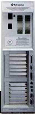
Power switch, a reset button, a front panel lock, and a four-character LED
display. The LED shows both diagnostic and system status information. For
example, "R" when reading the hard disk and "W" when writing to the disk. If
you press the Control or Shift keys, the LED shows the current system
speed.
Looks like it uses a HDLX-2416
display (also used on the Model 95 Op Panel).
Detail of the control panel HERE.
You control the 286 and 386 CPU Board speed with the Ctrl/Alt/+ combination
to raise the speed, or Ctrl/Alt/- to lower it. The system beeps once each time
you lower its speed, and twice each time you raise the speed. You can also use
a Wells utility, SPEED.EXE, to set the speed from the DOS command line."
On the standard setup disk are DISP.EXE and SCROLL.EXE, with which you can
display four characters of your choice, either statically or scrolling from
right to left, in the LED display. The Wells American ROM BIOS was the
CompuStar Multi-Processor Convertible Microcomputer V 1.05 BIOS." (Ed. which
might be an AMI based BIOS)
|
Size: 24 x 7.5 x 26 inches; 66 lbs (weight from 50 to 90 lbs,
depending on configuration)
All this AND a nice 8580-style handle!
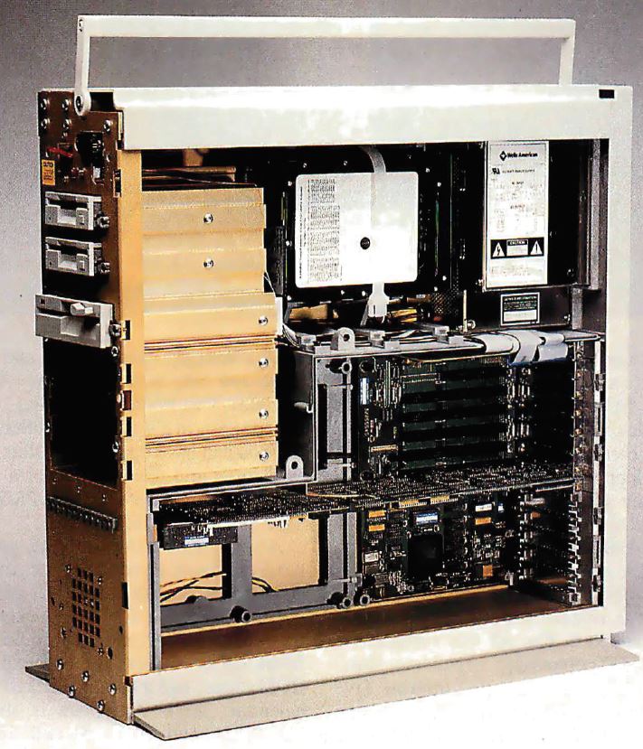
Finally we can see where the CPU board is, in the center. It seems to be
held in place by a ISA style slot bracket on the rear end, and by a plastic peg
at the front.
See the hard drive cables coming off the top AT card? That might be an
Adaptec ACB-2320 10-megabit-per-second ESDI controller in the top AT slots.
"Fans - one at the bottom front of the unit that blows out enough air that
you can feel it if you wear shorts, and one at the top rear inside the power
[supply] case."
Switch selectable 115/230 V 220 W power supply.

The "L" shaped board to the right of the speaker and to the left of the Bus
Backplanes is the "PS/2 Bus Module". Note the AT bus only system lacks ANY
board to the left of the Bus Module socket area...
Notice the black connector sockets on the right edge of the PS/2 module? The
MCA Bus Module has a matching socket on it's left side. Notice the single AT
Bus Module -LACKS- a socket on it's left side. But it doesn't need one, since
the CPU Board plugs into the I/O Module via the ISA riser.
CPU Modules
The CPU module contains a CPU, a socket for a math co-pro, memory sockets,
the ROM BIOS, sockets for two expansion ROM chips, and a battery-backed
clock/calendar.
Multiple CPU classes available - 8086, 286, and 386 with different clocks
(386SX was planned but possibly never released).
All the CPU boards accept the standard Intel math coprocessors; the 386
boards can also take the Weitek math coprocessors.
8086 CPU Module
The 8086 CPU board runs at 5 and 10 MHz and can hold up to 2.5 MB of
120 ns RAM. EMS 4.0 support is built onto the board.
Important: The 8086 CPU board does not support the
PS/2 Adapter module!
286 CPU Module
Processor: 20 MHz 16-bit Intel 80286 (Harris 80C286); 10 MHz Intel 80287 math co-pro
RAM: 1 MB 16-bit 80 ns DRAM on 80286 CPU module, expandable to 16 MB
ROM: 128 KB BIOS ROM
Based on the C&T NEAT chipset.
The 80286 CPU board runs at 20 MHz with compatibility speeds of 6, 8, 10,
12, and 16 MHz. Three different oscillators
(20, 16, 12 MHz) are divided by a flip-flop divider in order to provide 10, 8,
and 6 MHz speeds. Control the speed with Ctrl/Alt/+ combination to raise the
speed, or Ctrl/Alt/- to lower it. The system beeps once each time you lower its
speed, and twice each time you raise the speed. A DOS utility, SPEED.EXE, can
set the speed from the DOS command line.
The board holds up to 16 MB of RAM (the second 8 MB require an extender
kit). Memory over 1 MB can be configured for any mixture of extended
(protected-mode) and expanded (EMS) memory.
Interleaved memory banks, one bank of memory recharges while the other is
ready to go... nice improvement on traditional two bank interleaving: If you
have four identical memory modules, it can do four way interleaving, so that
three banks are ready while one is recharging.
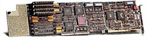
386 CPU Module "30055595"
![[P]](/other/img/photo.gif "Front") |
|
B1 RTC/CMOS battery (soldered in)
J1 I/O Module edge connector
J2 Bus Module Adapter edge connector
J3-10 30-pin SIMM sockets
OSC 40.1000? MHz osc
SRAM MB81C78A-35P 8Kx8 SRAM
U15 CHIPS P82C302(C) Memory Ctrl.
U32 A82385-20 Cache Ctrl.
U33 Math co-pro socket
U40 A80386DX-20 CPU
U47,51 CHIPS P82B305? Data Buffer
U49 CHIPS P82A304 Low Addr. Buffer
U53 CHIPS P82A303 High Addr. Buffer
|
U54 ROM BIOS Odd
U55,60 ROM sockets
U58 CHIPS P82A306 Control Buffer
U59 ROM BIOS Even
U63 CHIPS P82C301(C) Bus Ctrl.
U73 K/B controller?
U77 CHIPS P82C206 IPC
W5,6 Bus type jumper?
W7 Monitor type jumper
W11 NPU disable jumper
W? Unknown jumper
Y? xtal
Y2 RTC xtal?
|
W5,6 Bus type jumper? Pins 1 & 2 closed - MCA, pins 2 & 3 closed - ISA.
W7 Monitor type jumper. Pins 1 & 2 closed - Mono/CompuStar, pins 2 & 3 closed - Color.
W11 NPU disable jumper. Open - NPU enabled, closed - NPU disabled.
Processor: 16, 20, or 25 MHz 32-bit Intel 80386; Intel 80387 or Weitek WTL3167 math co-pro
RAM: 256 KB, 512 KB, 1 MB, or 2 MB 30-pin 80 ns parity SIMM modules, expandable to 16 MB
(modules must be installed four at a time)
Cache: 32 KB, 35 ns
Based on the CHIPS CS8230 386/AT Chipset. 82Cxxx are CMOS parts, 82Axxx are bipolar.
Different clock speeds available: 16 MHz, 20 MHz, and 25 MHz. Each also runs
at 10 MHz for compatibility.
I/O Module
|
DB25 RS-232C serial port
DE9 RS-232C serial port
DB25 parallel port
PS/2-style 6-pin DIN keyboard connector
PS/2-style 6-pin DIN mouse connector
Rectangular opening between lower PS/2 connector and DE9 Video might be a
board-mounted flip switch block to configure the DE9 video port...
DE9 digital connector
HD15 VGA analog. VGA, EGA, CGA, MDA, and Hercules graphics.
Paradise PVGA1A video chip
This board can handle up to four floppy disk drives.
|
Bus Backplanes
| AT Bus Module |
MCA Bus Module |
 |
 |
"The AT bus module has seven AT-compatible expansion slots, while the PS/2
module contains five Micro Channel-compatible slots and one AT-compatible
slot."
"You can pick an AT- or PS/2 Micro Channel compatible bus module; if you
choose the PS/2 bus module, you also need a special PS/2 adapter. The AT bus
module has seven AT-compatible expansion slots, while the PS/2 module contains
five Micro Channel-compatible slots and one AT-compatible slot."
If you look at the top image of an open case, there is a planar UNDER the
top AT Bus module. As there was no second Bus Module, you can see the planar's
lower half. Note that it does not extend past the black frame in the middle of
the case.
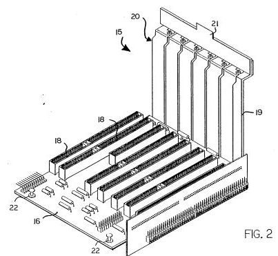
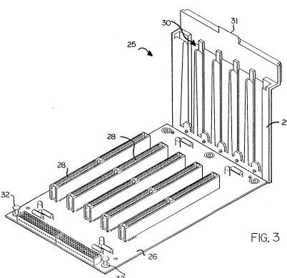
Looking at the case images, you can see the push-pin fittings, like in the
8570. Look at the patent drawings, and you will see the snap fittings on the
left end of the Bus Modules.
There must be some special mojo AT slot on the I/O module (I prefer to call
it a planar), and the "ISA" slot mentioned in articles -MIGHT- be the riser
which connects the AT bus looking edge contacts on the CPU card to the special
mojo slot on the I/O planar.
I was thinking in two dimensions while the CompuStar used that black frame
as a standoff in order to mount another set of PCBs above the I/O planar...
"So, in a single CompuStar chassis, you can have up to 13 AT slots, or 10
PS/2 slots and one AT slot, or a mixed bag of seven AT slots and five PS/2
slots." AT Bus Module has 6x 16-bit, 1x 8 bit, but the internal structure gets
in way of one slot so the limit is 13 slots. But there are only 11 externally
accessible slots...
Setup Disk
Includes Wells's setup program (also in ROM and accessible via the Ctrl/Esc
key combination); a LIM/EMS driver; system video mode utility; port assignments
and memory usage control (includes its use of interleaving and shadow RAM);
special disk drivers (including Extended Diskette Drive BIOS); and the LED and
compatibility speed control programs.
Options
CompuStar Base Model 100
AT-compatible primary bus module
AT-compatible secondary bus module
PS/2-compatible primary bus module
PS/2-compatible secondary bus module
PS/2 adapter module
8086 CPU module (does NOT support MCA Bus Modules)
80286 CPU module
80286 memory-extender kit
16 MHz 80386 CPU module
20 MHz 80386 CPU module
(25 MHz 80386 CPU module?)
Experiences
From Tom Sightler:
Well, just for the record, the Wells American CompuStar 95100 used
a modular bus that could have 8 ISA/EISA slots and 5 MCA in the same machine
(or 16 ISA/EISA). (Ed. See above for more accurate
slot count info.) I worked for this company back in 1989 and we were even
featured on the cover of Computer Shopper that year (Ed.
May issue)
with a picture of the machine with both an ISA and MCA bus in it. Of course, as
the rest of history goes, IBM sued (I don't think Wells properly licensed the
MCA technology) and the company went out of business sometime in 1990-91 (I was
long gone). I have no idea if any such machines are still out there, so I doubt
it's worth using this exception to worry about coexistance, but I still thought
you might find it interesting. At the time the CompuStar was advertised as
being the only computer that allowed you to leverage lowcost ISA cards as well
as higher performance MCA in the same machine, from this I would guess there
are no others, but who knows. A quick search on the web did find one reference
to this machine in someones collection, but I doubt it's in use, and even less
likely that Linux/MCA would run on it anyway.
From a former Wells American customer:
We had a similar problem with a company that recently went under,
Wells American in West Columbia, South Carolina. We ordered one of their
CompuStar 2000 386 machines with a convertible bus. Supposedly it was supposed
to have ISA, EISA, and MCA bus expansion boxes available for it. We wanted to
use it as a backup for our PS/2 file server, but as luck would have it, it
didn't have it built in, the "MCA expansion unit was forever on backorder" and
they used proprietary disk drive holders (they didn't use rails, rather they
used a plate which screwed on to the bottom of a 1/4th height - yes it was
1/4th height 5.25" disk drive. These parts could not be purchased anywhere. And
although a national company serviced the machines and could get the parts, they
could not sell them to the end user. When I called up and requested one, they
sent me the front cover to a 3.5" disk drive and some screws that fit
absolutely nothing on the computer. I finally send the computer back and a very
nasty letter on company stationary telling them that we cannot deal with any
companies that treat corporate customers in that way. I send it back.
From Michael Hoyle (original HERE):
After the A*Star, Wells American designed a dual bus 80286/80386
machine called the CompuStar I. This machine was a floor standing tower and was
designed with the first processor local bus. A separate motherboard held the
bus interface circuitry. The bus architecture could have been a combination of
Micro Channel or ISA. Only ISA was ordered as Micro Channel was a flop. The
CompuStar had a single board processor (proprietary design) that was
interchangeable. An 80286 machine could be switched to an 80386 in 10 min. The
case was built from extruded aluminum and was a hefty design. "The Robb Report"
picked the CompuStar I as the "Ultimate" computer and it received the highest
rating given to any hardware product by "InfoWorld" magazine for the year it
was reviewed. 386 processor speeds reached 16/20/25 MHz.
The CompuStar II in contrast was a very small machine. It had
interchangeable processor boards but only the ISA bus. It could mount 3 half
height 5.25" drives and a 3.5" fixed drive. Each of the CompuStar machines
could hold up to 16 MB RAM. 80386 Processor speeds were 16/20/25/33 MHz.
With the recession of 1988/9 the expensive CompuStar sales slowed and Wells
American could not keep up financially, declaring bankruptcy. The A*Star and
CompuStar trademarks were sold to CornerStone Technologies, Inc., in SC. The
A*Star is still manufactured by CornerStone.
I was the production manager when the A*Star was first produced and then
became the Product Manager for the A*Star and CompuStar lines. I am the
President of CornerStone Technologies, Inc. so I have been building the A*Star
since 1985.
| 