|
8555 PSU
Test PSU
Planar Power Connector Pinout
Hard-drive Power Connector Hack
Dead PSU
H032934 Intermittent, difficult-to-diagnose system problems
H095558 Surge suppressors and intermittent problems
8555 PSU (Used in 8530-286, 8555SX, 9553)
AA5992, IBM P/N 33F8138, GBM Number 27F4920 (Black Power Paddle)
API-8245, IBM P/N 27F4919, GBM 27F4920, FRU 27F4166
SMP-90EB, IBM P/N 33F8138 (Red Power Paddle)
Power Supply/Fan Assembly 27F4166
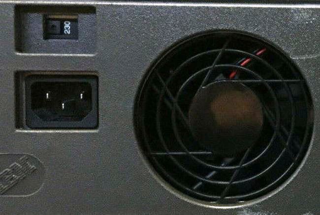
You must select voltage range with a switch on the rear of the unit. There
are two positions, "115" and "230". Switch color may vary between white, red,
and black.
AC Input:
100-125 V 2.4 A 50/60 Hz
200-240 V 1.4 A 50/60 Hz
DC Output: 90 W total
+5 V / 13.0 A
-5 V / 0.11 A
+12 V / 1.8 A
-12 V / 0.3 A
When the system is powered-off for 10 seconds or more and then powered-on,
the power supply generates a 'power good' signal that resets system logic. The
presence of the 'power good' signal indicates that the power supply is
operating properly and that the minimum under-voltage sense levels have been
established. This means that all system-board power requirements have been
met.
Test PSU
If voltages are not correct, or if fan is not running, replace power supply.
Power-off system. Remove power supply connectors P7 and P14 from system board.
Power-on system and check for listed voltages. If voltages are not correct,
check power cord for continuity. If power cord is good, replace power
supply.
Planar Power Connector Pinout
Connector J7 / P7
|
| Power Check P7 |
| V dc Min |
V dc Max |
-Lead Pin |
+Lead Pin |
| +4.8 |
+5.2 |
P7-5 |
P7-10 |
| +4.5 |
+5.4 |
P7-9 |
P7-5 |
| +11.5 |
+12.6 |
P7-5 |
P7-3 |
| +10.8 |
+12.9 |
P7-4 |
P7-8 |
Caution: Compared to the common "clone" PC AT
power supply pinout pin 2 is Ground instead of +5 V!
|
Connector J14 / P14
|
| Power Check P14 |
| V dc Min |
V dc Max |
-Lead Pin |
+Lead Pin |
| +4.8 |
+5.2 |
P14-1 |
P14-3 |
| +4.8 |
+5.2 |
P14-1 |
P14-4 |
| +4.8 |
+5.2 |
P14-2 |
P14-5 |
|
Ground is also shown as "DC RTN"
Hard-drive Power Connector Hack
From Peter Wendt, original HERE.
You will need:
- a soldering iron (a good one - not one for plumbers !)
- a multimeter with VDC and Ohms-range
- a sharp knife or cutter
- a standard power-connector (4 pins - maybe cut from a wrecked power supply)
- some insulation tape (hi-quality - not that lousy supermarket stuff)
- alternatively:
4 selfcutting wire-adaptors - like used to install additional equipment in cars
(from autoparts supplier)
- some self-confidence (like always)
It is a good idea to leave the cables on the power connector as long
as possible to make it fit on any device to be installed in a PS/2.
Please note that clone PC power cables use yellow/black/red, while IBM
systems use yellow/black, or red/black/blue. What is important is the position
of the conductor. Note that the drive power connector is keyed with beveled
edges.
What to do:
Method 1 - the solder solution:
- remove insulation at the 4 cables from the power connector for about 6 to 8 mm
- use a sharp knife or cutter and cut around into the insulation of orange cable at P3-3
Cut only the insulation - not the entire cable !
Distance to the white connector: about 2.5 cm (1 Inch)
Cut around the insulation again 3 mm away from the first cut
Cut between in the length of the cable (Care for your fingers !)
and remove the piece of insulation between
- repeat the same at the black cable at P3-6, the black cable at P4-1 and the red cable at P4-6.
- wrap the end of the orange (or yellow) +12V-cable from the standard connector around the open cable at P3-3 and solder it.
Wrap the black cables from the power connector around the open cables at P3-6 and P4-1 and solder them too.
Now wrap the red +5V-cable from the power connector to the open cable at P4-6 and solder it too.
- Use insulation tape to prevent short-circuits
- Check the new +12V / +5V lines for continuity
- Plug back the power cord into the power supply, switch it on and check the voltages between GND and +12VDC resp. GND and +5VDC with a multimeter
- If everything looks fine, Switch off, remove power cord and re-assemble everything, install new harddrive or whatever you want
Method 2 - the non-soldering solution:
- plug a self-cutting cable adapter over the orange +12VDC-cable at P3-3
Insert the orange (or yellow) +12V-cable from the power connector into the cable-adapter
Use a larger plier to press the connecting knife blade of the adapter into the two cables
Flip over the protection lid on the adapter
- Repeat the previous step with the black cables of the power connector and cables P3-6 and P4-1
- Repeat the procedure with the red +5V-cable and cable P4-6
- Check the new +12V / +5V lines for continuity
- Plug back the power cord into the power supply, switch it on and check the voltages between GND and +12VDC resp. GND and +5VDC with a multimeter
- If everything looks fine, Switch off, remove power cord and re-assemble everything, install new harddrive or whatever you want
Alternatives on Model 55 with the Mitsubishi MF355C Floppy Drive
The lot of Model 55 that I know are equipped with the Mitsubishi MF355C Floppy drive unit. It has dual pinrow 34-pin connector. If you look at the underside of the PCB where the 34-pin connector sits you find 2 markings:
Pin #3 marked "5V" and
Pin #6 marked "12V"
An equivalent GND-return is pin #33.
If you solder your DC standard-plug cable here it will do too. The frequently used ALPS drives have the same pinout - but here the DC-pins are not explicitly marked.
But: the power drawn via the very thin FDD connection cable should not be too high. You should use one of the later "low power" harddisks, like the IBM DORS, which does not exceed a power draw over 4 Watts in operation / 6 Watts at startup.
(Thanks to Michael Flinck for pointing out the differences and problems with the Model 55, which I left
a bit unclear.)
Warnings and recommendations
The maximum power drawn from this power connector is below 1 A for 5 V and 12 V
However: if you removed the original harddisk and installed a modern-type
harddisk (even with an additional SCSI-controller) the whole thing will do fine.
Remind, that the power-supplies aren't that powerful at all.
Maximum power on Model 30 and 55 power-supplies is:
- +12 V: 1.80 A
- +5 V: 9.00 A
- -5 V: 0.11 A
- -12 V: 0.30 A
Which is a total of 70.75 Watts
Dead PSU
Peter wrote:
One reason why it might appear as dead is, when for example a
monitor is placed on top of the unit and the mechanical pressure through the
monitor on the top cover presses down the vertical riser-card, so that the pins
at the underside of the planar board get shorted against GND on the case. This
was pretty familiar mistake one some series of Model 55SX.
I would recommend to remove the top cover, all MCA adapter cards and detach
the harddrive cable from the riser-card and try if the system comes up
again.
On some few occasions the 55SX suffers on a defective power supply, which
did not send the "Power Good" signal to the board and this therefore does not
come out of the pre-POST status (no reset, no Power On Self Test, all
subsystems deactivated).
> A problem developed with the 55SX Power Supply. If I flip the switch the
system is dead, but if I leave it that way with the power on in about 5 to 10
minutes the system will boot normally. One time starting up I got a 1XX error
with a few question marks underneath. and the system crashed with a stack error
System Halted, and after flipping the switch and waiting fifteen seconds the
system refused to power on, but after sitting ten minutes the power came on and
the fan started moving.
Stephan Goll:
Hello Mike. I believe, you are right with the power supply. But
there is voltage up to 1.5 KV (?) insight, and it's not funny to get shocked by
this. But if you try, there must be a resistor (near the high-power capacitors)
inside loading a small capacitor, that supports voltage for the low-voltage
powered control-electronic. May be the resistor or the cap' (or something else)
is wrong (and that is simplified). The 55 PSU contains only one board, not that
complex, but be warned. Really only for people, they know, what they do.
Learned by experience. ;-|
H032934 Intermittent, difficult-to-diagnose system problems
Intermittent and very difficult to diagnose system problems, may be caused
by line cords which are not fully seated, or are too loose to make a tight
connection.
When troubleshooting intermittent post errors, or any unusual, system
problems, (for example; system performs power-on reset unexpectedly during
operation) check the line cord for proper seating. Slight forming of the male
contacts in the system unit power supply connector may correct the problem.
Replacing the line cord may be necessary in some cases. Both ends of the line
cord should be checked.
H095558 Surge suppressors and intermittent problems
There is no requirement for external surge suppression devices on IBM PC
(Personal Computer) or Personal System/2 products. The power supplies in these
systems have been designed to meet IBM corporate requirements that include
factors considered adequate for product protection.
If intermittent problems are being experienced, and normal troubleshooting
efforts have failed to isolate the source of the problem, and an external
"surge suppression device" is being used, try running the system without it. If
the problems no longer occur, suspect the surge suppression device to be the
source of the problem.
Surge suppressor facts:
- External surge suppression devices have been known to be the source of
difficult to diagnose system problems.
- No universally accepted design or performance standards, such as IEEE or
ANSI, have been established for these devices, therefore design and performance
vary between vendors, or models.
- There is no practical way to test them in the field.
- Recent research reveals surge protectors may contribute to LAN crashes by
diverting surge pulses to ground, thereby contaminating the reference used by
data cabling.
There are several surge suppression devices available on the market, however
the most commonly encountered device is the MOV (metal oxide varistor). MOVs
have a failure mode of "shorting" when subjected to surges beyond their peak
ratings, and are subject to "MOV degradation" over time, which reduces their
value as surge suppressors.
|