|
187-132 3151 ASCII Display Station
189-071 New Models And Enhancements (510/560 and 610/660)
Common Problems and Questions About 3151 Terminals
3151 Models (a bunch of tables)
3151 Errors (stub)
GA18-2633-0
3151 ASCII Display Station Guide to Operations May, 1987
GA18-2634-0
3151 ASCII Display Station Reference Manual Apr, 1987
GA18-2654-0
3151 User's Guide for Cartridge to Emulate IBM / DEC Terminals Apr, 1987
CONSOLE_fix_T4.zip Makes the "ASCII Terminal" option available (more info HERE)
IBM 3151 ASCII Display Station
3151 / 3153 Keyboard
Communication Ports
ASCII Terminal on the 8595 / 9595 / 95A
Missing ASCII Terminal Selection
Video Calls under Console Mode
Can Serial Console Support be Added to a Model 90?
Opening and Closing the 3151
IBM 3151 ASCII Display Station
The IBM 3151 ASCII Display Station is a two-element workstation that
provides attachment capabilities to both IBM and non-IBM processors. A native
mode and 10 non-IBM emulation modes are included in the base of all models. The
Model 110 should be used for entry level applications requiring an 80-column
display. Models 310 and 410 (which are functionally identical to each other
except for the color of the display phosphor) should be used with applications
that require 80- or 132-characters-per-line capability, 3101 emulation, a
dedicated numeric keypad, Program Access (PA) keys, greater than 12 function
keys or RS422A capability via cartridge. Additional emulations and attachment
capabilities are provided in two new slim-line cartridges for Models 310 and
410.
The IBM 3151 Cartridge for Emulating IBM and DEC Terminals provides the
ability for IBM 3151 Models 310/410 and 360/460 to support RS422A
communications for the emulations provided on that cartridge. The RS422A
interface supports a point-to-point direct coupling with a maximum cable length
of 4,000 feet.
The main communications port has a selectable transmission rate from 50 bps
to 38,400 bps, inbound and outbound XON/XOFF pacing (inbound pacing is the
default and not selectable), and echo/character/block modes, and supports
seven- or eight-bit word length and no/odd/even/mark and space for parity.
The auxiliary port on the 3151 Model 110/160 is a unidirectional RS232C port
for attaching another asynchronous ASCII device such as an ASCII printer. On
IBM 3151 Models 310/410 and 360/460 the auxiliary port is enhanced with a
bidirectional data capability. This allows the attachment of output devices,
such as a printer, as well as input devices, such as wands and ASCII terminals.
Transmission rates from 50 bps to 19,200 bps are selectable independent of the
main communications port speed settings.
3151 / 3153 Keyboard
The 3151 and 3153 keyboards are not interchangeable. The following is a
diagram of the modular RJ keyboard connector:
| Pin |
3151 Signal Name |
Pin |
3153 Signal Name |
| 0 |
NO CONNECTION |
1 |
KBD CLOCK |
| 1 |
FRAME GROUND |
2 |
KBD DATA |
| 2 |
+5V |
3 |
RESET*(pulled up to +5V) |
| 3 |
KBD DATA |
4 |
SIGNAL GROUND |
| 4 |
KBD CLOCK |
5 |
+5V |
| 5 |
SIGNAL GROUND |
6 |
FRAME GROUND |
| 6 |
FRAME GROUND |
|
|
| 7 |
NO CONNECTION |
|
|
These pins and connector drawing are relative to the connector on the 3151,
3153 video element. These pins and connectors are not relative to the connector
on the keyboard coiled cable.
Note: Even though the 122-key terminal keyboard
is not officially supported by the 3151, it works just fine.
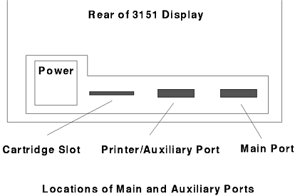
Communication Ports
If you look at the back of the 3151, the main port is on the right-hand
side, closest to the edge. The auxiliary port is closest to the power cord.
ASCII Terminal on the 8595 / 9595 / 95A
The 8595 / 9595 / 95A supports the specialized use of some ASCII display
stations instead of a display and a keyboard. The following IBM ASCII display
stations can be attached to a serial port: 3151, 3161, 3162, 3163, and
3164.
Keep in mind if you plan to use an ASCII display station:
- Verify operating system supports an ASCII display station. Not all do.
- BASIC language is not supported.
- High-resolution graphics (icons and graphic-based programs) are not available.
- Power-on self-tests (POST) text messages and logs are not available.
Use the setup instructions that came with your ASCII display station and the
information in this section to attach it to your server.
Notes:
- Use a null-modem cable or adapter. Without one, the ASCII display station
has no communications link with the server.
- If your ASCII display station has a test switch next to the keyboard
connector, make sure it is in the normal position, not the test position.
- When using system programs to define setup values on the ASCII display
station, be sure terminal machine mode matches the actual display station.
Example, if installing a 3151 ASCII Display Station, you must set Machine Mode
on terminal Setup Menu to IBM3151. When the setup values correctly match the
display station type, the machine is considered to be in the native-machine
mode.
To set up your ASCII display station
Attach null-modem cable [or adapter] to
the ASCII display station. Connect the other end to one
of the serial connectors on the server.
Note: For
95A systems, if serial port power-on mode is enabled,
attach the ASCII display station to serial port B.
Connect power cord to server; then plug it in.
Connect power cable to ASCII display and plug it in.
Turn on ASCII display station [is it in
native-machine mode?]. (See note 3) Set the communication values on display
station:
- Press Ctrl and Setup to display General Setup Menu.
- Press Send to display Communication Setup Menu.
- Review communication values and compare them to the values shown below.
         Line Speed (bps)             9600
         Word Length (bits)              8
         Parity                         No
         Stop Bit                        1
- To change a value, move cursor to highlight it, then press space bar to
display alternative values.
- When all communication values match the values specified in this section,
press Send twice to display Function Menu.
- Move the cursor to Save data field and press space bar to store these
values.
Notes:
- When using system programs, do not install an emulation cartridge unless it
will support native-machine mode.
- The display stations designed for countries where English is not the native
language must support the ISO 8859/1.2 code page. Some display stations require
a cartridge to support this code page.
- For additional information about communication values, refer to the
documentation that was supplied with your ASCII display station.
Verify that all the correct values have been stored:
- Move cursor to Recall
data field. This displays current communication
values. (Your server uses these during
configuration process.)
- Press Ctrl and Setup to exit. Only the cursor will be displayed on the
screen.
- Start system programs.
If you are using a keyboard and a display:
- Insert Reference Diskette in diskette drive.
- Turn on server and allow POST to finish.
- Press F1 to view Main Menu of system programs.
Change Console Select settings to select an ASCII display station.
Warning! Before making changes using Console
Select program, make sure you have an ASCII display station attached to server.
If you do not, there will be no way for you to communicate with the server.
When you are at Main Menu,
- Select Set features; then, press Enter.
- Select Set console from the Set Features Menu; then, press Enter.
- Select ASCII display station from Set Console Menu; then, press Enter.
- Make sure the values are set as shown:
         Baud rate               9600
         Bits per character         8
         Parity                  None
         Stop bits                  1
Any time you change the ASCII display station values, you must also update
the system unit values to match. The baud rate should always be 9600 or above.
If you set the baud rate below 9600, the system performance decreases.
Note: These instructions assume that the display
station has already been set to these values (see step 3 of this
procedure).
Some server operations change when you use an ASCII display (see the
following).
Communication When using an ASCII
display station, the communication parameters will appear on the 95's
information panel (example, 96-8N1). This is not an error message.
Configuration When you run the server
setup programs, system programs, or diagnostics programs from the ASCII display
station, the display station values might change. If display problems occur
after you run these programs, check the display station values. To check these
values, press Ctrl and Setup. Modify the values if necessary.
Utility Programs To start the server
system programs when using an ASCII display station, insert the Reference
Diskette into the startup drive. Turn on your server.
Note: To restart your server after running the
utility programs, press and hold Ctrl, then press C, A, and D. Release C, A,
and D. Then, release Ctrl.
Diagnostic Tests When you select an
ASCII display station as the system console, the keyboard, mouse, system board
async port, and video displays will not on the diagnostic Installed Device
list.
Missing ASCII Terminal Selection
Anyone know why I don't have the option for an ASCII display under Set
Console? I tried it on my 9595-0LF and 9595-3PT. Neither one has it. The
9595-0LF did go into "96-8N1" mode by itself about a month ago but it won't now
that I want it to! I have a "IBM Cartridge to emulate IBM and DEC terminals"
P/N 94X4114. Of course nothing works with or without it installed...
Hi Dennis!
You need a nullmodem cable for the terminal and no cartridge
installed (native mode). The terminal test switch must be in "normal".
There should be a chapter on using the ASCII console in the EPRM...
Workaround
The 9595 should be configured to "keyboard and videoless mode" somewhere in
additional features. Then the video card must be removed to force the machine
to kickstart the ASCII-terminal at COM1.
Issue Fix (by Major Tom)
The "ASCII Terminal" option is not available because of a bug in the
CONSOLE.COM program on the reference disk. The utility calls Int 15 func. 3Dh
subfunc. 01h and then checks bit 17 of reg. EBX. Based on its value it then
allows or disallows the two additional console options: "ASCII Terminal" and
"No Console". The problem with this is that the bit in question is *never* set
for any of the supported planars (the bitfield is hardcoded and never
modified). This check is not present in any other version of the CONSOLE.COM
utility (afaik). It's possible that the CONSOLE.COM code is actually correct
and it's the BIOS bitfield what's wrong, but the result is the same and the
CONSOLE.COM program is easier to fix.
I've modified the CONSOLE.COM binary so it checks bit 16 instead - bit that
is *always* set for the supported systems. You can download the patched binary
HERE. Extract the file and copy it to your
Type 4 reference disk, replacing the original file. You can then optionally
run the "Update System Programs" option to copy the new file to the convenience
partition on your hard-drive.
Video Calls under Console Mode
Major Tom has conducted painful probulation and reports:
In the console mode they are overriding all video calls (Int 10)
with a special table that transforms it to some special serial port calls
(undocumented Int 14 functions 60-64 - exclusively used by the serial console
code), and they are doing some magic with keyboard buffers as well. I think the
serial console mode should work fine in most "well behaved" text mode
applications.
That's what I wanna test... It will also help me figure out meaning of some
of the CMOS, NVRAM, and EBDA fields.
Quick & dirty list of the undocumented Int 14 functions:
Int 14 AH=60h - Initialize and attach CONSOLE Device
Int 14 AH=61h - CONSOLE Input
Int 14 AH=62h - CONSOLE Output Character (AL - char)
Int 14 AH=63h - CONSOLE Output String (ES:SI - string ptr)
Int 14 AH=64h - Remove CONSOLE Device
Incomplete and not quite confirmed yet, I will have to put more work into
this. The serial console stuff is not a priority, and I'm just mapping what is
what at this point.
Ed. Tom: This has since been confirmed by
the US5193174 patent, names of the
listed routines were modified to match the "official" ones.
Can Serial Console Support be Added to a Model 90?
The serial console mode is explicitly disabled on Model 90 directly in the
POST code. It checks the planar ID, and if it's FF6Fh, it completely skips the
serial console initialization code. Not sure if there is any technical reason
for this, or if they did it just for market segmentation reasons, but I could
easily patch the ROM to see whether that's enough to enable the console on
Model 90.
Some other patching may be necessary though, as to enter the console mode on
my 9595 I had to physically remove the video adapter from it. Changing the
console settings, and disconnecting my keyboard and/or monitor wouldn't do it.
And Model 90 has the always present on-board XGA... Maybe this was just a
PEBCAK though, as I didn't have much time to play around with it.
Ed. Tom: It's possible to force the ASCII terminal
mode with a fixed CONSOLE.COM binary (see HERE).
So, the serial console mode may be possible on some of the late PS/2
machines (will have to check the ROMs), but it would be fairly difficult to add
it to the older systems. There is A LOT of code related to the console mode in
the ROM, and it's spread all over the place. Even thinking about backporting
all that to the older POST/BIOS code gives me a headache.
Opening and Closing the 3151 (by Major Tom)
If your terminal has the optional tilt stand, remove it first (it's locked
in place by two plastic latches, see
Guide to Operations
page 26 physical for details).
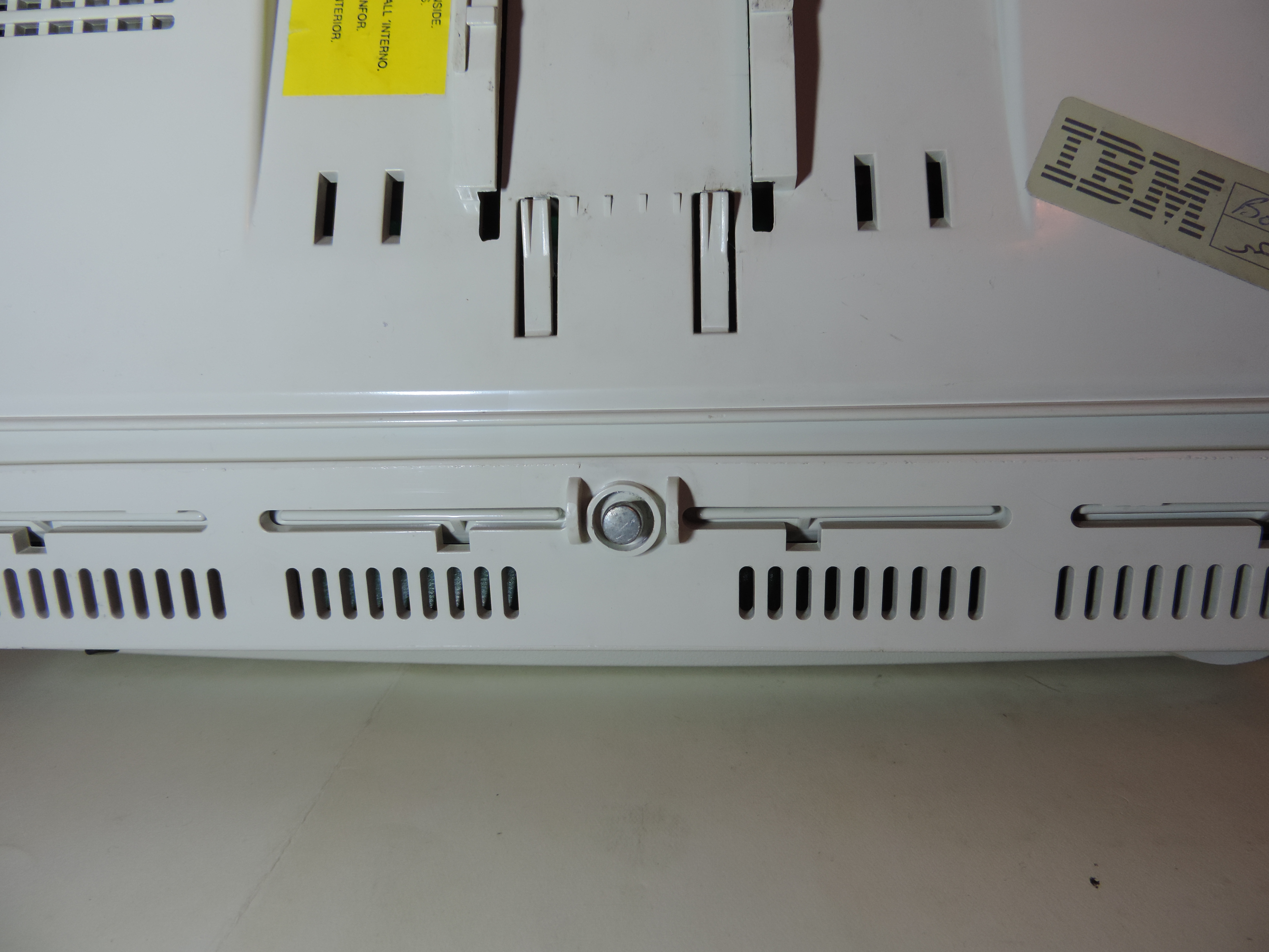
The entire case is held together by a single screw and two large plastic
clips. First, you need to undo the screw at the bottom of the case... which is
where the first problem comes up. The screw has a round, completely smooth,
head with rounded edges. To make things even more complicated, there's a
plastic ring around the screw (see the pictures below).
Probably the easiest way to remove it would be to take a Dremel and cut a
groove into the head (don't cut too deep, we don't want the head to split), and
then use a flathead screwdriver to undo it. Be aware that this method will
likely damage the plastic ring around the screw unless you have a cutting wheel
with a very small diameter and really steady hands...
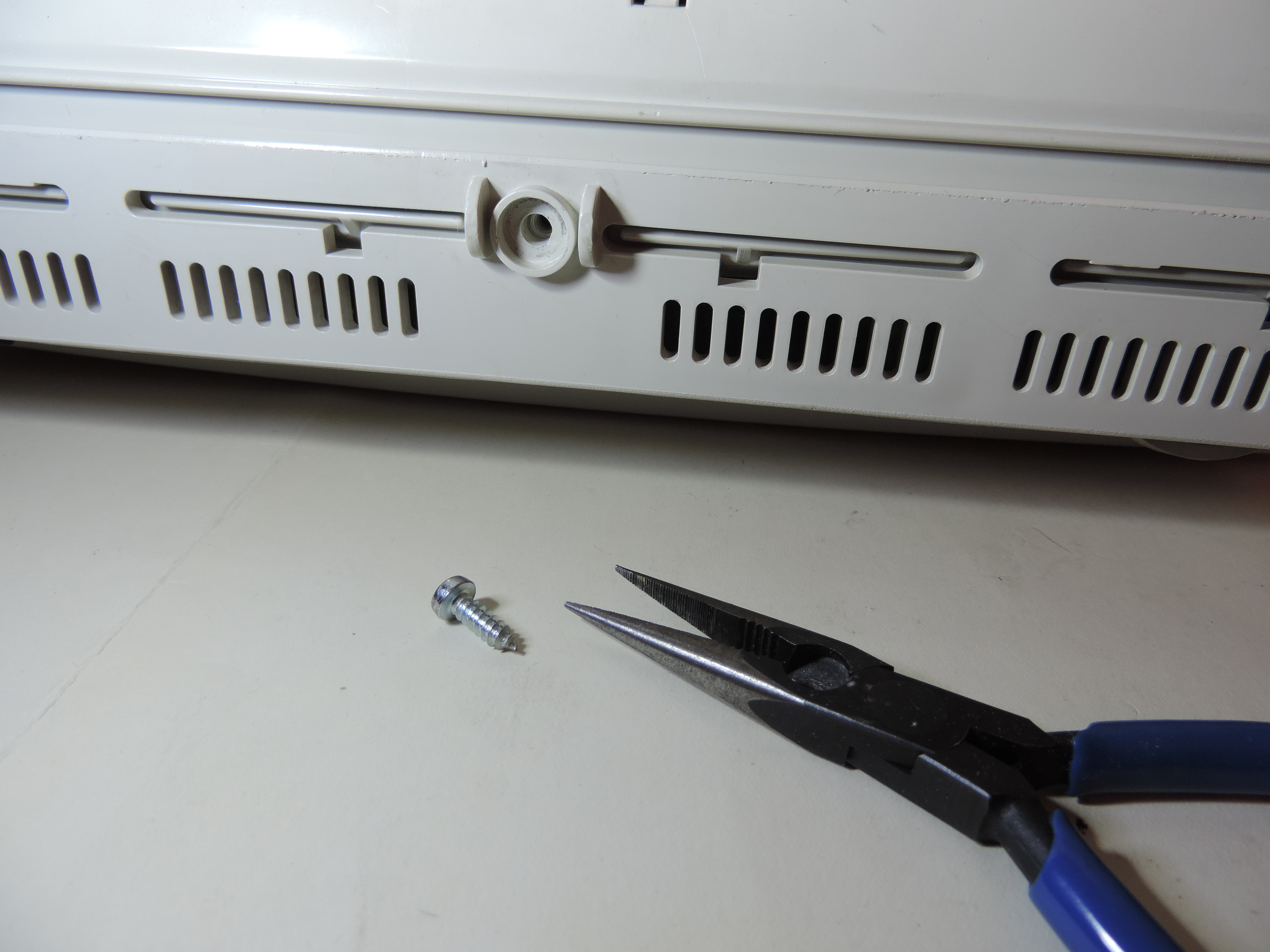
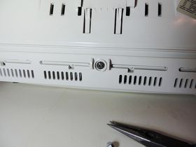
Alternatively, you can try grabbing the head with a pair of fine nose pliers
(small wire cutters could work as well) and unscrew it that way. It helps if
you mark the head with a sharpie or something, so you can tell if the screw is
actually turning or just slipping. If you are lucky the screw isn't in too
tight, and if you manage to turn it a bit, you are pretty much set, it only
gets easier as you go. This is the method I've used and it took me probably 5
minutes to remove the screw, with a minimal damage to the screw "well". You can
press on the plastic to make it bend inwards and give yourself an extra
millimeter of depth to work with. YMMW.
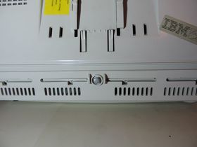
The annoying anti-tamper screw |

And the winner is... nose pliers! |
With the screw removed, you should be able to split the bottom side of the
case - don't open it too much however, you could break off the plastic tabs at
the top side of the monitor (they would probably unclip before breaking, but
the plastics are getting brittle, so I wouldn't risk it). Normally there are
two openings that can be used to unclip the tabs, but not here! Wegh... turn
the monitor around, so you can access the top side easily and try shoving
a piece of plastic or paper (i.e. a business card, or a credit card if it
fits...) between the two halves of the case (towards the front face) starting
in the corner and working it towards the center. The two tabs are only some 3
cm from the corners and about the same distance deep. This way you should be
able to unclip one side and then the other, setting the back cover free.
Something tells me that IBM doesn't fancy the idea of you poking inside one
of these things very much...
Warning: The picture tube acts as a large
capacitor and can hold a charge of several thousand volts for prolonged periods
of time! Discharge it with a grounded screwdriver before removing the anode
cap! The capacitors on the PCB can be charged to a few hundred volts! Improper
manipulation may lead to an injury, death, fire, and/or other damage. The
author is not responsible for your actions and their consequences. Proceed at
your own risk!
The internal metal shroud is not held in place by anything but friction, and
the same is true for the PCB (be careful when removing these items, you don't
wanna "neck" the picture tube!). The entire thing is rather cheaply made.
There's a single board inside that holds the PSU, the flyback, the digital
circuits, and even all the connectors and controls. The backup battery is
solder in, the serial connectors lack the metal shielding... certainly not up
there with the PS/2 line quality-wise.
When putting the thing back together, make sure that the PCB is seated
correctly inside the case - the front controls must be aligned with the front
panel openings. The metal shroud goes *over* the metal tabs that are attached
to the PCB, not the other way around. Before you clip the case together, check
that the serial connectors, the card slot, and the power socket are all aligned
with their respective holes.
Much better... |
And finally, replace the annoying "anti-tamper" screw with a normal one -
try to match the diameter and thread pitch if possible.
The original is: AVSAFE (thx Louis) self tapping screw, d=4 mm, l=13 mm (w/o head), head d=7 mm.
|