|
Understanding
New Developments in Parallel Ports Douglas Boling,
PC Mag Oct 27, 1992
PC Magazine issue, Vol 11, No. 18 Google
Books HERE
Scanned and OCR'd, available on Internet
Archive HERE
Parallel Port Controller
(Hardware Interface Technical Reference, Oct 1990)
Ed.
Folks, I have been bedeviled by the IBM DMA parallel port
and it's odd behavior with enabling DMA. I have read the
HITR, and it was (as with most IBM technoslovakian)
relatively obtuse. Recent research into Parallel port CF /
SM / MMC readers drew my attention to SPP / PS2 / EPP /
ECP modes... A recent revelation - so what if the IBM
parallel port is fed from serial DMA? The devices would
never know. No idea, though, about possible programming
issues.
Do pay attention to the MDA' s printer port at 3BCh, it
certainly suggests why IBM PS/2 systems use Parallel_1
with 3BCh, why Parallel_2 at 378h is the clone LPT_1, and
why turning on the DMA on Parallel_1 actually shifts the
registers up into the 127Xh range...
I'm always looking for material specific to using or
programming for parallel ports on Micro Channel systems.
If you have, or know of, further items, please
Contact Us.
Understanding the New Developments in Parallel Ports
by Douglas Boling
Serial ports send data relatively slowly over long
distances, while parallel ports provide rapid transmission
across short distances. I discussed serial ports in the
Lab Notes columns of May 12 and 26, 1992; now it's time to
turn to the other common input/output (I/O) port. As
before, I'll try to cover both the basics and new
developments, in this case culminating in the Type 3
bidirectional printer port of IBM's PS/2 series and
Intel's Fast Mode parallel port.
The beauty of a parallel port lies in the simplicity of
its design. When the computer sends a byte of data to a
parallel I/O port, eight data lines transmit the entire
eight-bit byte at once. The I/O port matches the eight
bits of the byte to eight different pins on a connector,
and the external device attached to the connector can then
read the data at its leisure. (In practice, an extra line
is usually used to indicate that the data on the pins is
valid.)
While normally used to send data to a printer, a parallel
port can be connected to a variety of external devices. In
the early days of computing, when most computers came as
kits to be built by hobbyists, the parallel port was used
to read a set of switches for input, flip relays to
control machines, or blink little lights for the amusement
of the curious. Most hobbyists' computers used a parallel
port to scan the switch matrix that formed the keyboard
for the system, and indeed the keyboards on most PCs to
this day are read through a parallel port on the keyboard
controller.
THE
PC'S ORIGINAL PARALLEL PORTS
Like serial ports, most parallel ports on early computers
were bidirectional: The data lines could both send and
receive data. When IBM introduced the PC, however, it was
meant to be a small business computer; the neat uses to
which hobbyists could put a parallel port were not a
consideration. Businesses didn't need to flip relays or
blink lights, but they did need to print documents. Thus,
the generic parallel port was specialized to talk to the
standard Centronics printer interface.
IBM offered two versions of parallel ports on the original
PC. One version was attached to the Monochrome Display
Adapter (MDA), which I'll call the MDA printer port; the
other was located on the separate Parallel Printer
Adapter.
The MDA printer port was the more popular, since it
provided a printer connection without the need for an
extra card. (The original PC motherboard had only five
slots, remember.) The design of the parallel port on the
MDA card and the parallel port on the Parallel Printer
Adapter were almost identical, however, with their only
difference being the starting addresses of the I/O
registers used to control the port. The MDA printer-port
registers started at I/O address 3BCh, and the printer
adapter registers started at I/O address 378h.
The design of the PC Printer Port differed from that of a
generic, hobbyists' parallel port in two main ways. The
first was in its adding a number of control lines to the
eight data lines. Figure 1 shows the lines on the MDA
printer port and their connector pin assignments. These
control lines allowed the PC to control the printer while
allowing the printer to return
status information to the PC. The second major way the PC
Printer Port differed from others was in its data lines,
which were not bidirectional but for output only. The
output-only nature of the port provided enough
functionality to send data to a printer, but it limited
the usefulness of the port for other tasks.
In other respects, the MDA parallel printer port followed
the usual conventions. The voltage levels on the pins (or
lines) are the standard Transistor-Transistor Logic (TTL)
voltage levels of 0 and 5 volts. A value of 0 is
represented by a voltage of 0 to 0.8 volts, and a value
of 1 is represented by a level of 2 to 5 volts. When a
line is said to be lowered it is simply being changed from
a 1 state to a 0 state. Raising a line means the line is
being changed from a logic 0 state to a 1 state.
MDA Printer Port Connections

As shown in Figure 1, the Data Register lines in the MDA
printer port are unidirectional: Data can be sent only
from the computer to the printer. The control and status
lines allow for a minimal handshaking protocol to transfer
the data to the printer.
Of the four control lines, the first three (SLCT IN, INIT,
and AUTO LF XT) initialize and configure the printer. The
SLCT IN line tells the printer that it should get ready to
accept data. The INIT line initializes the printer, and
the AUTO LF XT line tells the printer to move
automatically to the next line when a line of text has
been printed. The fourth, STROBE control line, tells the
printer that a new data byte is ready to be read.
The five printer status lines return information to the
PC. The SLCT OUT line indicates that the printer knows it
has been selected. The BUSY line indicates that the
printer is busy and cannot accept data. The PAPER END line
indicates that the printer has run out of paper. The ERROR
line indicates the printer has detected an error
condition.
The fifth, ACK line, indicates that the printer has
accepted the data from the computer and is ready to read
another byte. This line is special, since the printer port
can be configured to interrupt the processor with a
request for more data when the ACK line is lowered.
As with such system peripherals as disk controllers and
serial ports, the CPU controls the parallel port through
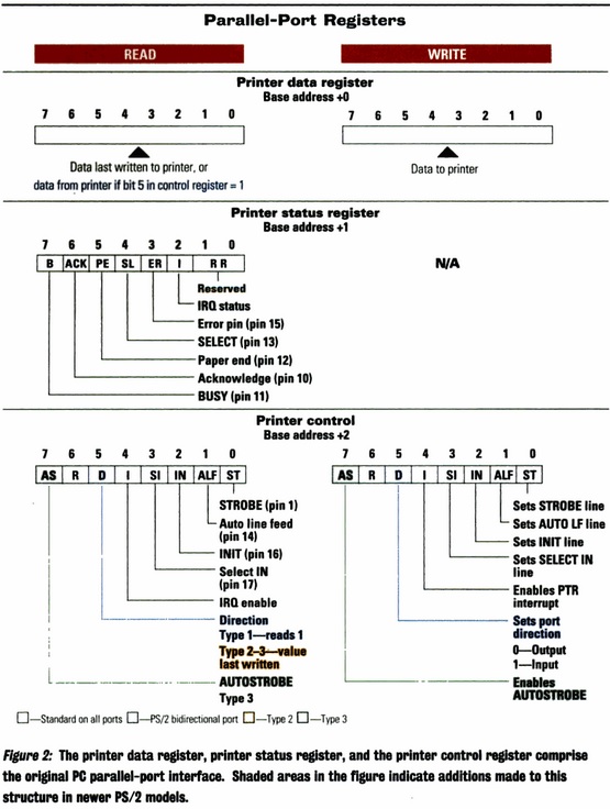
I/O registers. Figure 2 details the three registers that
make up the standard register level interface for PC
parallel ports. The printer data register sends data to
the printer, the printer status register reads printer
status, and the printer control register sets the printer
control lines. The features that have been added in later
revisions of the port structure are shown by shaded areas
in Figure 2.
As with the registers for the serial port, the
parallel-port registers are accessed through the IN and
OUT I/O instructions. The starting address of the
parallel-port registers are listed in the BIOS data
segment, starting at 40:08. While the registers of the MDA
printer port start at I/O address 3BCh and can't be
changed, newer printer ports can be addressed at a variety
of I/O addresses, typically starting at 378h and 278h.
Writing a byte to the parallel-port data register sends
that byte to the port. When the data register is read,
however, the byte returned is the data currently being
sent by the printer port. This would seem to indicate that
the MDA printer port is inherently bidirectional. The
problem is, however, that there is no way to tell an MDA
printer port to stop sending data.
In other words, the printer port can't listen for any data
coming from other devices connected to it simply because
there is no way to tell it to stop talking! If another
machine does attempt to send data across the data lines
(something that should not be done with the MDA printer
port), the data read would be a combination (logically
ORed) of the data being
sent by the MDA port and the data being sent to it.
The port status register, however, allows the processor to
read the port status lines (SLCT, BUSY, PAPER END, ERROR,
and ACK) from the printer. Writing to the printer status
register has no effect. The status lines thus provide the
port with a rudimentary input capability. This ability to
read in data-albeit a nibble (four bits) at a time-is in
fact utilized by many file-transfer programs.
For example, two MDA ports can be made to talk together if
the pins are specially connected for this purpose. If the
lower four data bits from one PC are connected to the
SLCT, BUSY, PAPER END, and ERROR lines of a second PC, the
one PC can send four bits of data out its MDA printer
port. The other PC reads that data on its MDA printer
status lines. To send data back, a similar connection is
made in which the second PC's lower four parallel-port
data lines are connected to the first PC's printer status
lines. While the ACK line could be used as a fifth bit to
read data in this arrangement, it is better employed
allowing one PC to interrupt the other to indicate that
the data has been or is ready to be read.
The printer control register allows the processor to
manipulate the control lines of the printer interface.
Unlike in the serial interface, all the handshaking must
be performed directly by the processor. As with the data
register, the data written to the port control register is
immediately passed to the output pins of the printer port.
Note in Figure 2 that bit 4 of the port control register
is not connected to a control line; it is used instead to
enable the parallel-port interrupt. Once enabled, the
parallel port will interrupt the processor when the ACK
line is lowered. The parallel port is normally assigned
hardware interrupt 7. Reading this register returns the
state of the same control lines being sent to the printer.
Before concluding this discussion of the standard PC
parallel port, it is important to clarify one confusing
characteristic of the PC parallel port (and of all other
digital hardware): the concept of a negative
active signal. This is important if you
ever attempt to relate the state of the bits in the
parallel control and status registers with the voltage
levels of their corresponding pins on the port connector.
Some of the control signals on the printer port are
negative active. This means that the signals are
considered present when the line carries a logical 0
instead of a 1 value. To compound the confusion, some of
the control lines in the parallel port are inverted before
they reach the pins on the connectors. That is to say,
writing a 1 value to a bit in the printer control register
results in a logical 0 on the actual line. Some of the
bits in the printer status register are also the inverse
of the voltage levels on the pins.
Specifically, the lines that are inverted from the bits in
the control register are STROBE, AUTO LF XT, and SLCT IN.
BUSY is the only other line that is inverted from its
corresponding bit. Other status register signals, namely
ACK and ERROR, are negative active, but the corresponding
register bits are not the inverse of their pins.
PS/2
BIDIRECTIONAL PARALLEL PORTS
When IBM introduced the PS/2 series in 1987, the parallel
port was rescued from its printer-only captivity. While
retaining backward compatibility with the printer adapters
of the earlier PCs, the parallel port on the PS/2 machines
was redesigned to include the bidirectional capabilities
of pre-PC parallel ports.
Restoring bidirectional capabilities simply required
making it possible to turn off the data lines from the PC,
thus allowing data from another source to be sent on those
lines. With the PC no longer sending data, a read of
the printer data register returned the data being sent
from another device attached to the port.
To set the PS/2 parallel port to read mode, a previously
reserved bit in the printer control register is used to
establish the direction of the data. Specifically, setting
bit 5 to 1 configures the parallel port for input. The
port itself must be configured to allow bidirectional
mode. On PS/2s the parallel port can be set up in
bidirectional mode by using the configuration disk that is
provided with the machine.
Other manufacturers have also introduced a bidirectional
parallel port on their machines. The parallel ports in
some machines that use the Chips & Technologies chip
sets are compatible with the PS/2 parallel port, for
example. Not all competing machines have followed the IBM
PS/2 standard for controlling the direction of the port,
however. The Toshiba machines use bit 7 of the port
control register instead of bit 5, for example. As with
the PS/2s, the parallel port in clone machines must be
configured for bidirectional operation. This is usually
done with a setup program specific to the system.
Parallel Port Registers
Note: The OCR has
removed most of the colors from this artwork. I will
replace this if I find something better...
THE TYPE 3 PARALLEL PORT
The bidirectional port on the original PS/2 was called a
Type 1 parallel port. The new PS/2 Models 57, 90, and 95
have what IBM calls its Type 3 parallel port. (The IBM
hardware reference also covers a Type 2 parallel-port
controller, which is slightly less capable than the Type 3
controller.) The Type 3 port can use a DMA (direct memory
access) channel to write or read an entire block of data
to the port without assistance from the processor. The
discussion below will center on the Type 3 controller, but
the differences between the other two bidirectional
controllers will be noted as appropriate.
From its introduction in 1981, the PC has had a DMA
controller. The DMA controller is a chip that does nothing
but move data around in memory. If the CPU needs to move a
block of data, it can delegate the job to the DMA chip
while it does more productive things. A DMA chip usually
has a number of channels, each of which can move a block
of memory
or move data to and from an I/O port.
Like a DMA channel, the Type 3 parallel port can run
independent of the CPU. In DMA mode, the DMA chip and the
parallel port talk to each other without the help or
interference of the CPO. In DMA mode, the parallel port
uses the STROBE, ACK, AUTO LF XT, and BUSY lines to
control data transfer between the PS/2 and an external
device. The only tasks the CPU must perform are to set the
parallel port into DMA mode and to configure a DMA channel
to read or write data. Once configured, the DMA channel
automatically reads a byte of data from memory and writes
it to the data register of the parallel port.
Once data has been written to the data register by the DMA
channel, the parallel port automatically lowers the STROBE
signal. This indicates to any device attached to the port
that the data lines are ready to be read. Once the
receiving device has read the data, it in turn lowers the
ACK line to indicate that fact. The Type 3 parallel port
then automatically raises the STROBE line and signals of
data to the data register. The cycle is then ready to
begin all over again, continuing until the DMA controller
has sent the entire contents of its buffer. At any point
the receiving device can suspend the data transfer by
lowering the BUSY line.
When configured in receive DMA mode, the DMA controller
waits until the ACK line changes from a 1 to a 0 state.
The port controller detects this change, lowers the AUTO
LF XT line, and then reads the byte from the data
register. Thereafter the port controller raises the AUTO
LF XT line and lowers the STROBE line to indicate that the
data has been read. The Type 3 parallel port can be
programmed to interrupt the CPU when the DMA operation is
complete.
DMA Mode PS/2 Connections
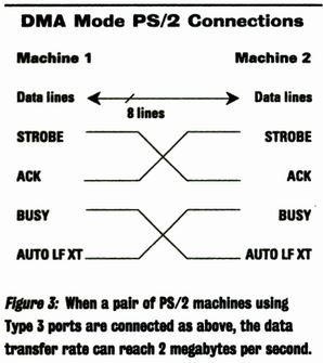
If two PS/2s are to transfer data using the DMA mode,
their two parallel ports should be connected in the manner
shown in Figure 3. This particular configuration allows
the two parallel-port controllers to produce the proper
handshaking for the DMA transfer.
So connected, a pair of PS/2s using their DMA parallel
ports can transfer data at up to 2MB per second, a
transfer rate rivaling that of some hard disk controllers.
And this speed is available with almost no work from the
processor.
The DMA mode was not the only improvement made in the Type
3 port. The port also has expanded interrupt capabilities.
The parallel-port controller can interrupt the processor
on changes in the ERROR, PAPER END (PE), and SLCT. Like
all previous parallel ports, the new port can also
interrupt the processor when the ACK line is lowered.
Three new registers were added to the parallel-port
register set to control the enhanced Type 2 and Type 3
parallel ports. This presented a problem when the port was
configured at the old standard starting I/O address of
3BCh, because if the new registers were placed at their
logical location (Just after the other port registers)
they would overlap the registers that control the VGA
palette. To solve this problem, the Type 3 parallel port
can be addressed at two different I/O address ranges if
configured as parallel port 1. When the parallel port is
configured as LPT 2, 3, or 4, the dual addressing is not
necessary.
Note: I have noticed
the odd addressing in planar ADFs for extended mode
Parallel_1, and it confused the heck out of me. My guess
is the move of the registers to 127Xh confuses the heck
out of non-MCA aware programs.
PS/2 Type 2 and 3 Port Addresses
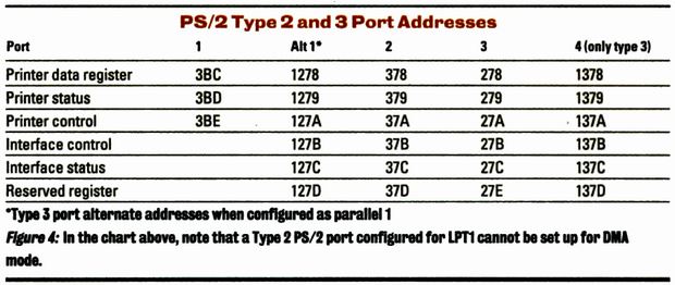
The possible I/O address ranges for PS/2 Type 2 and 3
parallel ports are shown in Figure 4. The Type 2 parallel
port cannot be set up for DMA mode when configured as
parallel port 1. Parallel-port registers start at I/O
addresses 378h, 278h, and 1378h for ports 2, 3, and 4,
respectively. Note that while these addresses are valid
for IBM PS/2 parallel ports, they are not necessarily
those used on other machines. The Printer Port Base
Address fields in the BIOS data area are the best place to
determine the printer port addresses.
Figure 5 shows the three new registers for the PS/2 Type 2
and 3 parallel ports. The first of these is the read/write
interface control register. This register enables and
controls the DMA process, and it also selects the
conditions for interrupting the processor. Writing a 1 to
bit 7
(Start DMA) initiates a DMA transfer. Setting bit 6 (Reset
End of Data Latch) enables the DMA channel to read from
the parallel port in response to the ACK line. Bit 1 (Set
End of Data Latch) stops a DMA transfer. Finally, bit 0
(Enable DMA) enables the DMA function. Only the limited
combination of the bit settings shown below are valid for
these bits.
New Type 2 and 3 Register Bits
| 7 |
6 |
1 |
0 |
Description |
| 0 |
0 |
0 |
1 |
No change to DMA operation |
| 0 |
0 |
1 |
0 |
Disable DMA |
| 0 |
0 |
1 |
1 |
Halt DMA or enable DMA |
| 0 |
1 |
0 |
1 |
Set ready to start DMA in
receive mode |
| 1 |
0 |
0 |
1 |
Start DMA in Send mode |
The remaining bits in the interface control register
enable the different interrupt conditions for the port.
Bit 5 enables an interrupt when the DMA controller
completes its transfer or when the End of Data Latch is
set and a change in the ACK line is detected. Bit 4
enables an interrupt when the SLCT signal is changed,
either from a 0 to a 1 or from a 1 to a 0. Bits 3 and 2
enable interrupts from the ERROR and Paper End (PE) lines,
respectively.
The Interface Status register allows the processor to
determine the source of a parallel-port interrupt and
determines the status of a DMA transfer. Bit 6 indicates
if a DMA transfer is complete or if it has been stopped
using the End-of-Data bit in the interface control
register. Bits 5 through 2 indicate the source of an
interrupt caused by the parallel port. Bits 7,1, and 0 are
reserved.
The last of the new registers is officially reserved by
IBM, except that it must be loaded with a value of 16h
before using the DMA mode of the port.
Note: Both Type 2 and
Type 3 controllers must load 16h. See the HITR for
details..
THE
386SL HIGH-SPEED PARALLEL PORT
Intel has taken a different approach to the design of a
high-performance parallel port. The company's new 386SL
chip is a low-power, two-chip package that integrates a
386SX processor with the logic needed for a laptop
computer. Included in the 386SL is what Intel calls its
Fast Mode parallel port.
Note: I do believe
some PS/2s use the 386SL.
IBM's Type 3 parallel port is designed to move large
chunks of data very fast without assistance from the
processor. This type of parallel port is best suited to
multitasking environments in which the processor has
better things to do than sit feeding data to a slow
printer. In contrast to IBM's DMA parallel port, the Intel
design is aimed at speeding the access to intelligent
peripherals attached to the parallel port.
With the growth of laptops in offices, an entire industry
has been built around peripherals that attach to laptops
without requiring an expansion slot. While external modems
have been around for years, the most interesting slotless
peripherals are the new LAN adapters that attach to -and
make new demands on- the parallel port of a laptop.
Note: Think of the
Xircom parallel port attached Pocket Ethernet and Token
Ring adapters.
Both the parallel port and intelligent adapters are
controlled by registers. While printing a document is
largely a matter of pushing massive amounts of data out
the parallel port, communicating with an intelligent LAN
adapter involves control as precise as if the LAN
adapter were a card plugged into the expansion bus. The
problem is that with only eight bits of data being
transferred at a time, any access to an intelligent
adapter register must be proceeded by an address that
specifies the register to be read or written. Further,
since the port must be used for both address and data
transfer, the control lines must be used to tell the
peripheral both what is coming across the port and how to
react to it.
Suppose that the processor needs to write to the LAN
adapter. It must start with a write to the printer control
register to set the handshaking bits indicating that an
address is coming and that the access will be a read of a
register in the adapter. The address is then written to
the printer data port. The LAN adapter takes the address,
places the data on the parallel port, and sets a control
line (such as ACK or BUSY) to indicate that the data is
available. The processor then reads the status port to
find out that the LAN adapter has the register data
available. Only at this point can the data be read from
the parallel port. All of this elaborate handshaking takes
time, and for peripherals such as LAN adapters, speed is
important. To
streamline the process, then, the Intel Fast parallel port
automatically encodes the handshaking information on the
control lines.
Intel 386SL Fast-Mode
Configuration
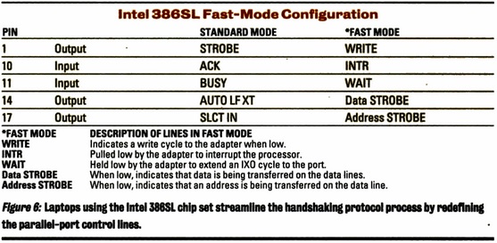
As you can see in Figure 6, when operating in Fast Mode,
the Intel port redefines the standard parallel-port
control lines so that they become bus control lines. The
SLCT IN line becomes the Address Strobe, AUTO LF XT
becomes the Data Strobe, STROBE becomes the
Write line, the BUSY line becomes the Wait line, and the
ACK line becomes the Interrupt Request line. This allows a
full complement of control lines to make the parallel port
into a mini-expansion port.
The Intel port uses different I/O addresses to encode the
control information. While the Intel port has the standard
data, control, and status registers of any parallel port,
its Fast Mode also has five additional I/O addresses,
which are located just above the standard addresses. If
the parallel-port base address is 3F8h, the I/O addresses
3F8, 3F9, and 3FA are the addresses of the printer data,
printer status, and printer control registers as expected.
What is different
about the 386SL printer port is the use of the I/O
addresses immediately above the three standard I/O
addresses.
I/O address 3FBh is the automatic address of the strobe
register. A write to this register sends the data to the
parallel port, just as writing to the data register would.
In addition, however, a write to the strobe register
automatically lowers the AUTO LF XT line, which is defined
as the Address Strobe line. A read or write to addresses
3FCh through 3FFh reads or writes the port and also lowers
the Data Strobe line (SLCT IN). If the data access to
addresses 3FCh through 3FFh is a write, the Write line
(STROBE) is lowered. When the processor writes to the
automatic Data Strobe addresses, the read or write I/O
cycle is extended if the adapter lowers the Wait (BUSY)
line. This allows the adapter to slow the processor to
match its speed without the processor even knowing about
the wait.
A peripheral attached to the 386SL's parallel port simply
looks at the control lines to determine what is coming
across them. If the Address Strobe line (AUTO LF XT) is
low, an address is being sent to the peripheral. If at the
same time, the Write (STROBE) line is high, the 386SL is
expecting the peripheral to return the data for that
address back to the SL. Otherwise, the SL sends the data
to be written to the address. At any time, the peripheral
can slow down the process by holding down the Wait (BUSY)
line. The SL will wait until the Wait line is high before
ending the current read or write.
This automatic encoding saves a tremendous amount of
needless handshaking through the control lines. By
eliminating the need to set the control lines manually,
accesses to registers on the adapters can be made in half
the time.
Like its serial cousin, the parallel port has grown
significantly in functionality. IBM's DMA parallel port
and Intel's Fast Mode parallel port represent two
different enhancements aimed at two different
applications. These new parallel port designs will
contribute tangibly to
better computing performance in the future.
DOUGLAS BOLING IS A CONTRIBUTING EDITOR TO PC MAGAZINE.
|