|
@6127.ADF Future Domain MCS-700 / MCS-600 with TMC-1800 chipset
@60E9.ADF IBM PS/2 SCSI-2 with TMC-18C50 chipset
@5F77.ADF Future Domain MCS-350 (no discrete SCSI controller chip! Uses PALs)
@5F77.ADF Future Domain SCSI Adapter (different memory ranges, more options)
@5F77.ADF Priam SCSI Adapter (different name, text & choice order)
IBM SCSI-2 Adapter/A Option Disk v1.00 For IBM/FD SCSI-2
Descriptor files for the MCS-350, MCS-600 and MCS-700
powrscsi.exe PowerSCSI
powscsi4.exe PowerSCSI4
Future Domain's SCSI Device Analyzer
US5544326 Interface and control
circuit for regulating data flow in a SCSI initiator with multiple host bus
interface selection (18C50 used on FD MCS-700 / IBM Patriot)
Design
of the software interface for a multimaster bus system
The Future Domain Story (archived)
OS/2 Switches
MCS-200
MCS-350
MCS-350 ADF Sections
MCS-600/700 Adapters
MCS-600
MCS-600 and the DB25
MCS-700 & IBM SCSI-2
Install MCS-600/77/SCSI-2 Under W95
Patriot Power Connector
SCSI-2 on IML System
Lacuna Convenience Partition
Long MCS-700 (TMC-1800 Based)
Adapter BIOS
FD and IBM Card Differences
FD/SCSI-2 and P70 ESDI
Running with the Devil (FD without ROM)
Drive Shows up as "Direct Access" (Use FDDSU.EXE)
MCS-600/700 TMC-1800 ADF Sections
MCS-600/700 or IBM SCSI-2 (18C50 chipset) ADF Section
1047000 221 POST Code
This error is caused by running a Patriot with nothing attached. You might
see an I9990303 as well if the Patriot has kicked an IBM SCSI controller with
the system partition out of the way, which is really confusing when you have a
Type 4 Flash based complex installed... I fixed this problem with an
Autoconfigure. Then the system booted normally.
Adapter Origins
The SCSI-2 Adapter /A was OEM'd by Future Domain, based on the MCS-700.
Early Future Domain branded MCS-700 SCSI controllers may use the TMC-1800 SCSI
controller AND the termination resistor arrangement of the MCS-600. The MCS-700
/ 600 can do Narrow-Fast of up to 10MB/s to the SCSI bus -BUT- only 3MB/s to
the MCA bus. Please remember the Future Domain was designed (successfully!) to
be a secondary SCSI adapter.
Future
Domain Ships Trio of Single-Chip SCSI-II Adapters
"Boards based on the chip can implement MFM-compatible BIOS parameters,
allowing AT or MCA computers to interact with SCSI drives as if they were
standard MFM hard drives. This capability will allow use of products such as PC
Kwik disk caching (Multisoft) or Speedstor (Storage Dimensions) that modify
drive parameter."
Future Domain's PowerSCSI includes Win3.11 32-bit disk support... I always
wondered how, since I don't remember other SCSI controllers that also support
32-bit under WfW. Also, is this due to the FD BIOS, or is it due to the
chipset?
18C50 vs 1800 Based Adapters (from David Beem)
> What are the differences between the TMC-1800 and TMC-18C50?
The TMC-18C50 had the improvement of a jumper-selectable termination instead
of removable resistor packs.
The external SCSI connection was a high-density DB-50 instead of the 'Apple'
DB25 connection of the MCS-600. Shrouded internal SCSI connector (helpful for
the right orientation every time) & un-implemented solder pads for jumper
settings than could adjust some SCSI bus options on the MCS-700 as well
(artifacts for floppy? The FD ISA SCSI-2 has similar jumper block). The MCS-700
power connector was more conservatively rated at 1.5 amps for the 12VDC and
5VDC pins, versus the 2 amp rating on the MCS-600. Of course "C" in the chipset
number means the power-saving CMOS fabrication.
I have to see if these different chipsets return different values for the
Future Domain BIOS call "Get SCSI Controller Information" INT 13h, Function
18h. The book I have shows only values for the older FD chipsets. There is
another BIOS call that determines ANSI SCSI-1 or SCSI-2 compatibility. Of
course the TMS-700 will have a much newer BIOS as well. On the versions I have
the boards are remarkably similar despite the 3 year difference in production.
Tiny differences that add up on the finer points of manufacture.
SCSI Chips
(from HERE)
"The TMC-1800 chip [was] completed in 1990. The 1800 chip, which supported
the 16 bit AT and MCA bus, had several design flaws that required hardware and
software to work around. As a result it lacked the compatibility of the 8 bit
chip."
The FD design is PIO, not a busmaster. If you have a heavily loaded system,
or one with low powered CPU, you might look for a busmaster. If you have a
486DX class system (or above) chances are the PIO will work just fine, because
the CPU has more than enough clock cycles to service it.
MCS-200 (Also Quantum MC-200S)
F1 Termpwr PTC
J1 External DB25 SCSI connector
J2 Internal 50-pin SCSI header
RP1,2 Resistor Pack RKL 10S101G
U1 BIOS ROM
|
U3 40.850 MHz osc
U4 8Kx8 SRAM
U9 FD TMC-1800
VR1 LT1086CT voltage reg.
W4 Termpwr Jumper
|
U4 8Kx8 SRAM Toshiba TC5588J-20, ATT
7C185J-20 or compatible
F1 The Termpwr fuse is a PTC Resistor
which goes to high resistance if too much current flows while providing
Termination Power to the SCSI devices. When the overload is removed, the PTC
resistor cools down and allows normal operation.
MCS-350 FCC ID HK9224MCS350
![[P]](/other/img/photo.gif "Front")
J1 External DB25 SCSI connector
J2 Internal 50-pin SCSI header
J3 Drive power Molex connector
|
RN2-4 RKL8B221/331/G
U11 FD BIOS V1.0E BB
U12 2Kx8 SRAM
|
U12 2Kx8 SRAM
UMC UM6116-3 or compatible
There is no integrated SCSI controller. The controller functionality is
implemented using PALs and 74xx logic.
AdapterID 5F77 Future Domain SCSI Adapter
Memory Location
Memory location used for the BIOS ROM
<"Segment CA00"
(ca00-cbff)>, C800 (c800-c9ff), CC00 (cc00-cdff), CE00 (ce00-cfff),
D000 (d000-d1ff), D200 (d200-d3ff), D400 (d400-d5ff), D600 (d600-d7ff), D800
(d800-d9ff), DA00 (da00-dbff), DC00 (dc00-ddff), DE00 (de00-dfff)
DMA Arbitration Level
DMA channel used to transfer data.
<"Level 6">, 7, 5,
0, 1, 3, 4
Select Interrupt Line
Interrupt used by the SCSI controller
<"Interrupt 5
(Reserved)">, 3 (Serial Alternate), 10 (Reserved), 11 (Reserved), 12
(Mouse), 14 (Fixed Disk), 5 (Reserved)"
Use Front Panel Disk Busy Light
Whether the front panel light is to be used by the SCSI devices to
indicate that a SCSI device is busy. The same light is also used by the
internally installed hard drive. There is no conflict if the same light is used
by both devices.
<"Use Front Panel
Light">, Do Not Use Panel Light
Use MC BUS Wait (IBM Model 80)
Extended synchronous bus cycle is used as the default fastest
cycle on the transfer of DMA data to the SCSI device. The Model 80 will not
support full speed DMA writes via the uChannel bus, so this option is required
for high speed devices on the Model 80.
<"Use Wait State (Model
80)">, Do Not Use Wait State
MCS-600/700 Adapters
MCS-600
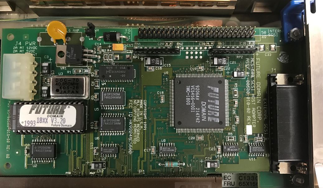
This shows the MCS-600 with a TMC-1800, no active termination, DB25 external
port, unshrouded 50 pin internal header, uses a 40.850 MHz osc, and has a 12 V
2 A and 5 V / 2 A rating (the SMD caps are 10 µF, 16 V)
MCS-600 and the DB25
Al Savage confided to the group:
Um, only the DB25 (early SCSI-1) used only one wire per data line,
with a combined data ground (unless I'm wrong). All the other SCSI wiring uses
a separate ground for every data line, which is why I sold off all my DB25
stuff and went C50 everywhere.
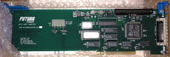
MCS-700 & IBM SCSI-2 "Patriot"
F1 PTC Resistor
J1 External HPDB50 SCSI connector
J2 Internal 50-pin SCSI header
J3 Pads or Molex power connector
SW? Pads for I/O and Base Addr. switches
U1 40.0000 MHz osc
|
U2 8Kx8 EPROM ROM BIOS
U4 8Kx8 SRAM (FIFO)
U7 Active terminator
U8 18C50 (L1A7620)
W1 Term. power jumper
W2 Term. enable jumper
|
U2 8Kx8 EPROM
NMC27C64Q-200 or
compatible
U4 8Kx8 SRAM (FIFO) NMS64X8AM20,
CY7C185-20 or compatible
U7 Active terminator -
REG5601U or UC80989DWP
W2 Term. enable jumper - Enables
integrated terminating-resistor. Remove if both INTERNAL and EXTERNAL SCSI -
devices are connected.
W1 Term. power jumper - Enables
terminating-resistor voltage and should normally be left in place.
SW? Pads for I/O and Base Addr.
switches
Four pins designated SW0-SW3 are provided to select the I/O and
memory base addresses. In a Micro Channel implementation these four pins
correspond to the Micro Channel POS bits 4-7. The I/O base address is given by
Table I below and the memory base address is given by Table II below. A 1 in
the Tables below corresponds to a grounded SW0-SW3 pin and a 0 corresponds to
an open or pulled-up pin. Address bits 17 and higher are decoded by logic
external to the multifunction SCSI chip.
Table I
SW1/
POS5 |
SW0/
POS4 |
Starting Address |
| 0 |
0 |
0140 |
| 0 |
1 |
0150 |
| 1 |
0 |
0160 |
| 1 |
1 |
0170 |
Table II
SW3/
POS7 |
SW2/
POS6 |
Memory Base
Address (Hex) |
| 0 |
0 |
0C8000 |
| 0 |
1 |
0CA000 |
| 1 |
0 |
0CE000 |
| 1 |
1 |
0DE000 |
Patriot Power Connector
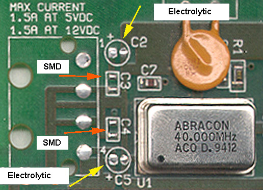
C2,5 10 µF 16 V electrolytic through-hole capacitors
C3,4 0.1 µF 16 V ceramic SMD capacitors (MLCC)
(capacitor values provided by Josh Behrends, thanks!)
Passive/Active SCSI Terminating
Passive terminating-resistors are normally fully functioning if only
internal or external devices are connected. If there
are internal and external devices connected you MUST
use ACTIVE -Terminating on both ends of the SCSI - cables (internal/external),
especially if there are fast Hard-Disks or any other FAST SCSI-2 devices (=>
10 MB/s) connected.
SCSI-2 on IML System
The 71G3575 will NOT support IML. They will lay an IML track, but can't
access the IML partition. No end of frustration... Do not try to use these in a
90 or 95 as an IML controller.
You can use the IBM SCSI-2 as a secondary controller where they work fine.
Hang a CD or a scanner off them. Nice to have a standard SCSI port to use (no
RS6K stuff).
Lacuna Convenience Partition
>Err ... Peter. All three of my 77s (9577-BTG) has a convenience
partition that was laid with the OEM'ed FD-MCS-700 that came standard. Same
thing goes for my 76s (9576-BNB).
That's what I said. The system partition will not work with the *original*
Future Domain MCS-700 without the "IBM Support BIOS" .... It works on the
IDE-machines (utilizing the IBM Int4B ABIOS extension hooked to generic BIOS
Int13h -which is the boot / harddisk interrupt- ... attached to hardware IRQ
0Eh) and on the SCSI Models only with the reworked IBM controller BIOS. Reason
why (to my opinion): the FD-controller can utilize other hardware IRQs than
only 0Eh (14).
My 9577-BTG has the IBM-version MCS-700 with the Rom BIOS 1.01 (I think) and
it has the "convenience partition" as well. I had the cached SCSI in that
machine as well - it also supports the partition, but is officially not
supported in the Lacunas.
Long MCS-700 (TMC-1800)
U4 appears to be a
Micron MT5C6408-20 8Kx8 SRAM.
Same size and speed (20 ns) as with the Patriot. Alternative pads for a .600
wide DIP; .300 DIP populated.
W1 is most likely TERMPWR. LT1086CT
voltage regulator.
W2 is fully populated - four jumpers.
The later short MCS-700 / Patriots have solder pads for a 4 jumper header. It
might be to set SCSI options on the TMC-1800 chip, but not needed on the
TMC-18C50.
Production around 9026. Huh, BIOS is undated, "MCS-700 V1.1", the MCS-700
TMC-18C50 based controllers start with 3.2 and go up to 3.61
The long MCS-700 is uncommon. Nice for collectors, but not too much, with
the butt-load of short MCS-700 / Patriots... Plus it uses the slightly buggy
TMC-1800 controller, the 18C50 fixed a few problems.
MCS-600/700 or IBM SCSI-2 under W95
Chances are, W9x won't get it right, and you might get a Future Domain
TMC-16xx series adapter installed. Which works, but not the best.
Manual Install
Control Panel>Add New Hardware>Future Domain (left hand scroll box)
> Future Domain MCS-600/700 (right hand scroll box).
Make sure the FD/SCSI-2 settings from under IBM's system programs (refdisk
or setup as you want to call it) are used. W95 knows the choices available.
Make sure the I/O and IRQ are correct! If not, you won't see a CD-ROM.
Adapter BIOS
BIOS Images
Uses 27C64 8Kx8 EPROM.
IBM BIOS v1.01 for FD MCS-700 card used in PS/2 Model 77s. 27C64-200
FD MCS700 BIOS 3.61 Future Domain MCS700 v3.61. 27C64-200
BIOS Versions
| Board | BIOS Version |
|---|
| 1.0 | 1.2 | 1.21 | 350
2.0 | 1800
1.0 | 1800
2.0 | 1800
3.0 | 3.2 | 3.4 | 3.5 | 3.6 |
|---|
| MCS-350 | X | X | X | X | | | | | | | |
| MCS-600 | | | | | X | X | X | X | X | X | X |
| MCS-700 | | | | | X | X | X | X | X | X | X |
After surfing ebay, I see that the 18C30 and 18C50 both use the V3.x BIOS.
The 18C30/50 use a mix of BIOS levels, for instance, there was a
TMC-1660, 18C30 with a V3.5 (94) BIOS. There was a TMC-1660, 18C50 with a
V3.01PM (92) BIOS. To guess, the 18C30 is a simple version of the 18C50.
Dunno.
V3.01PM 92 (OEM for Pinnacle)
V3.20 93
V3.3 93
V3.4 94
V3.5 94
Long MCS-700 (TMC-1800) BIOS
The Long MCS-700 (TMC-1800 controller) has an undated BIOS "V1.1 MCS-700", I
would guess about 1992?
FD and IBM BIOS Differences
Tim Clarke tossed this out:
For the Future Domain MCS-600/700 adapter ROMs:
a) Future Domain V3.nn = Future Domain and supports Int 13h via Int 4Ch
(SCSI-CAM). Does boot-drive scan from ID 0-6. (Peter)... but does not support
IBM's ABIOS functions which use Int 4Bh, which is the one that establishes /
handles a "convenience / reference partition". And which is the function that
reports back the attached SCSI devices. Max drive size directly controllable
with the latest Future Domain BIOS (v3.61, IIRC) it's around the 8GB mark
(actually 8064MB), as limited by the Int 13h BIOS call parameters' max. values
(1024-cylinders x 256-heads x 63-sectors x 512-byte sectors).
a1) Future Domain v3.4 - v3.5 (Reported by Cameron Labut)
Cameron was experiencing an odd behavior with a 8580 20MHz system
(Busmaster capable), 4MB on-planar, XGA1 w/512KB, and a Future Domain w/ V3.4
BIOS.
The system would boot with the XGA1/512KB, HDs and CDROM accessible. He
swapped in an XGA2 (1MB stock) and the HDs were inaccessible (but shows up on
FD boot message). CDROM is still accessible. This happened with the original
8580 refdisk and with the refdisk patched with XGAOPT. No XGA2 error messages were
displayed during POST, and the XGA2 passed advanced diagnostics...
After swapping in an IBM Patriot 1.01 BIOS, the XGA2 and all SCSI devices
were accessible at boot.
Ed. As we totally lack either the 18C50 or Future Domain BIOS references, we
can't be sure what the incompatibility is from. The incompatibility is most
likely NOT Busmaster related, since the 512KB XGA1 co-existed with the MCS-700.
Since the MCS-700 is PIO, that removes another possible conflict. No XGA2 error
messages suggest that the patched refdisk files are compatible with the XGA2
BIOS / hardware. The only thing not fully explored is IF a FD MCS-700
w/3.4 and XGA1 w/1MB was unable to access HDs. Hours spendt scouring the
internet only provided ONE possible significant issue, that of HD ordering.
This does not mean the HD ordering was the only issue with V3.4, but suggest
that V3.4 had issues.
Future
Domain BIOS 3.4 and 3.5 Hard Drive ordering
Please note that the drive ordering that Future Domain implemented in BIOS
versions 3.4 and 3.5 is the opposite of the order (currently) used by the rest
of the SCSI industry. If you have BIOS version 3.4 or 3.5, and have more than
one drive, then the drive ordering will be the reverse of that which you see
under DOS. For example, under DOS SCSI ID 0 will be D: and SCSI ID 1 will be C:
(the boot device). Under Linux, SCSI ID 0 will be /dev/sda and SCSI ID 1 will
be /dev/sdb. The Linux ordering is consistent with that provided by all the
other SCSI drivers for Linux. If you want this changed, you will probably have
to patch the higher level SCSI code.
b) IBM V1.0n = Supports Int 13h via Int 4Bh (IBM SCSI). Does boot-drive scan
from Id. 6-0 and supports RefDisk Config and Diags. If using the IBM v1.01
BIOS, it has a max drive size of 3.94GB (1024-cylinders x 255-heads x
63-sectors x 512-byte sectors), again IIRC.
> For using the MCS-700 as a secondary controller, allowing drivers to be
loaded, how big can the secondary drive be?
This is only limited by the driver's and OS's design, but has limits set by
a 32-bit "Logical Block Address" (LBA) of 4 Gigablocks and the assumed 512-byte
logical block size = 2 terabytes. Check your OS doc.s and any READMEs for the
driver for that OS.
Peter says:
1.00 seems to have limit at 4GB and -probably- with ATAPI CD-ROMs.
This is a "Lacuna"-specific problem when you have the harddisks attached to the
SCSI controller and an additional IDE CD-ROM on the planar port.
I'd tried that on a machine with IBM Controller BIOS Rev. 1.0 and the system
refused to even recognize the CD-ROM. I switched to a 1.01 controller and
-voilá- there it was. However: when I set the CD-ROM to "Slave" it failed to
work properly even with 1.01 on the SCSI controller.
There seem to be dependencies within the Boot BIOS part of the IBM SCSI BIOS
on the FD-controller. 1.01 works fine with bigger HDs and CDs... but dislikes
CD-ROMs solely attached to the IDE jumpered as "Slave".
Finally, Peter says:
The FD MCS-600/700 can be upgraded to an IBM SCSI-2 with the IBM
ROM. The two only differ by the DC-plug that the FD has and the IBM lacks. The
FD was originally designed as an "upgrade controller" to add to an existing
system which might not have a free DC-plug. The IBM version was intended as
"additional controller" (e.g. for tapes in a MCA Server) or sole SCSI
controller as in the Lacunas, which have enough DC-plugs coming from the power
supply. Just in case anyone wonders why IBM saved the few pennies for the
DC-plug.
SCSI-2 and P70 ESDI Adventures
Jeff Hellige vents and says:
I've got my P70 running again under OS/2 Warp Ver. 3 and
regardless of the slot it's placed in or the configuration, the MCS-700 seems
to be conflicting with the onboard ESDI controller in protected mode. POST is
reports the following error on bootup:
1047000 221
(ESDI Controller Wrap Failure)
If the SCSI board is left in, OS/2 will run for a while and then start
locking up, which makes sense if the conflict is in Protected mode. DOS will
run without errors. The Reference diskette diagnostics configuration report
shows the wrong configuration with the board install and I've not attempted to
go any further with the SCSI board installed. With it removed the diagnostics
goes all the way through without errors, showing the
correct
configuration.
The ROM version on the MCS-700 is 1.01. I've tried it in both slots as well
as tried changing the IRQ and such in the Reference disk setup. All of this had
no effect on the error.
reinstalled the MCS-700 with the IBM BIOS 1.01 still installed. It
continued to give the error and I ran diagnostics from the Refdisk. The SCSI
test gave an error of 0210000U. I removed the BIOS and reinstalled. PowerSCSI4 would not install without
a device hooked to the card so I connected an external 1gig SCSI hard disk to
it. Drivers installed fine under both DOS and OS/2. No errors on boot and I'm
able to access the drive fine under both operating systems as well. It took
4-1/2 minutes to copy 64meg of data from the internal DBA disk to the external
SCSI disk.
I had tried to disable the BIOS in the system setup on the Refdisk, but it
didn't help. Removing the BIOS chip altogether seems to have fixed it though.
My only complaint is that it insists on formatting the external hard disk with
32k sectors! I'll have to play with that some more. Now the question is, what
functionality have I lost by removing the BIOS chip? Am I correct to assume
that it won't be possible to boot off a SCSI disk in this configuration?
FD
w/o ROM
Tony roars with:
Setup a MCA flavor S/320 with one of the FD's (minus ROM) running
an Archive Viper tape drive. Nothing dramatic happened - it just worked. Nice
to free up one of my scarcer v1.01 IBM ROMs so I can replace the brain dead
v1.0 in something else. BTW, autoconfig seems to want to allocate a ROM address
for the adapter by default. I just went in after autoconfig ran and disabled
the (nonexistant) ROM.
Tim Clarke says:
That's because the ROM actually has only 6KB mapped-in and the
controller chip has a 2KB "buffer" that is configured to be contiguous with it,
to make up the 8KB total "ROM" allocation. I'm not sure if the "ROM Disabled"
configuration means that the buffer is too, causing some extra I/O overhead, or
not.
ADF File for MCS-600/700 board
(TMC-1800 VLSI) Version 1.1
AdapterID 06127h Future Domain SCSI Adapter
Adapter Memory Location
Memory location used for the BIOS ROM
<Segment CA00>,
Segment CE00, Segment DE00, Segment C800
Adapter I/O Location
I/O location the adapter will use
0140, <0150>, 0160,
0170
Select Interrupt Line
Interrupt used by the SCSI controller
<Int 5>, 10, 11, 12
(Mouse), 14 (HDD), 15 (Rsrvd), 3 (Serial Alternate), Int Disabled
ADF File for MCS-700 /IBM MC SCSI-2 adapter
(18C50 VLSI)
60E9 IBM PS/2 SCSI-2 Adapter/A or MCS-600/700
Adapter ROM BIOS Address
Memory address for ROM BIOS. Generally, the BIOS is enabled to
support fixed or removable SCSI disk drives. If you use PowerSCSI software, and
if the SCSI devices attached to this controller are tapes, CD-ROM drives or
non-direct access devices, the BIOS may be disabled to speed system startup
<Segment CA00>,
CE00, DE00, C800, Disabled
Adapter I/O Port Address
I/O port addresses the adapter will use
<0140h>, 0150h,
0160h, 0170h
SCSI Adapter Address (ID)
SCSI ID of the adapter is fixed and cannot be changed
<7>
Select Interrupt Line
Interrupt used by the SCSI controller
<IRQ 5>, IRQ 10,
IRQ 11, IRQ 15, IRQ 3, IRQ 14, Disabled
Direct Access Fix?
>I've tried to add a 2GB 0664 drive as ID4 to my system. The added drive
at ID 4 is listed as "direct access" instead of "hard disk," and no size is
listed. When I attempt to low-level format, the list of available drives does
not include the drive at ID 4. Can someone please tell how to revive the 0664
that responds as a "direct access" device?
The Magic Christian responds:
This requires a Future Domain MCS-600/700, IBM OEM'd version
(Patriot), or something else that can run the DOS utility FDDSU.EXE that comes
with 'Powerscsi4'
'The following procedure should read the firmware parameters from a SCSI
drive and then write those parameters back to the media. This will normally
restore a fixed disk to the factory default parameters. Not all drives will
support this procedure. Future Domain will not be responsible for the results
stemming from the use or misuse of this procedure.
- Insert the Future Domain "SETUP" utility.
- Type "SETUP" and press <RETURN>.
- A screen will appear displaying the SCSI ID and LUN of the drive.
- A menu will appear as follows:
- Format Unit
- Edit Defect List
- Surface Analysis
- Press the <F5> function key to invoke the Custom Utility menu.
- Message appears "you are about to enter the Custom Utility...", answer yes to continue.
- A menu will appear as follows:
- Format Unit
- Edit Defect List
- Surface Analysis
- Sense Byte Editor
- Choose option 4. Sense Byte Editor.
- A menu appears as follows:
- Mode Sense
- Write sense data to a file
- Read sense data from a file
- Print current list
- Edit current list
- Set options
- Choose option 6. Set options.
- A window appears and asks if you want to change Mode Select byte 1. Answer no.
- You are asked if you want to change Mode Sense byte 2. Answer yes.
- Enter the hex value "BF" and press <RETURN>
- The Sense Edit menu appears. Select option 1. Mode Sense.
- Now select option 5. Edit current list.
- Window opens up on left side of screen. These are the Page codes of the SCSI drive.
- Press <F7> function key. Message should say "Sense Info sent successfully".
- Press <ESC> twice to exit back to the main menu.
- Choose option 1. Format Unit.
- When asked "Permission to format", answer yes.
This should update the media with the parameters from the firmware. The
drive must accept and finish the low-level format for the above procedure to
work correctly. Also, some drives do not support a low-level format. When in
doubt check with the drive manufacturer."
Specs (PS/2 SCSI-2 Adapter/A and MCS-700)
| SCSI type |
SCSI-2 Fast |
| SCSI bus path / speed |
8 bit / 10 MB/sec |
| I/O bus path / speed |
16 bit / 3 MB/sec |
| RAID levels |
None (use software) |
| Tagged Command Queuing |
No |
| Processor |
None (PIO) |
| Channels |
One (internal/external) |
| Connectors |
One internal; one external |
| Devices supported |
7 devices per adapter |
| Cache std / max |
0 KB / 0 KB (8 KB buffer) |
OS/2 Drivers & Switches
The following drivers support Future Domain and IBM SCSI host adapters:
FD8XX.ADD - Future Domain TMC-845/850/860/875/885 (ISA)
FD16-700.ADD - Future Domain TMC-16xx,1790,1795,1800/18C30/18C50,3260/36C70
FD16-700.ADD - Future Domain MCS-600/700
FD850IBM.ADD - Future Domain TMC-850IBM
FD7000EX.ADD - Future Domain TMC-7000EX
FD16IBM.ADD - IBM 16-bit ISA SCSI Adapter
OS/2 driver switches see HERE.
|