|
Introduction
Opening the Case
Removing Internal Components
3rd party content (original archived HERE). Edited by Tomáš Slavotínek.
Introduction
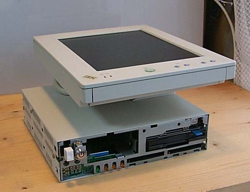
The unit displayed here is 5538-UWD, but the same disassembly process can be
used for -VWD, -VWC, and other models.
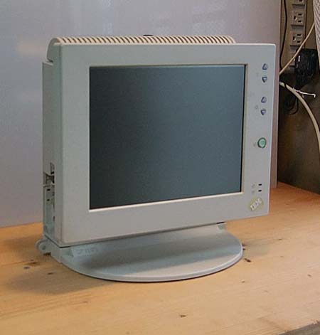
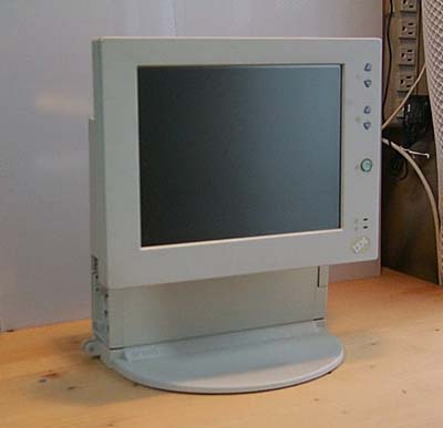
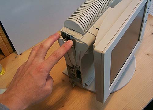
The LCD screen moves up and down like this.
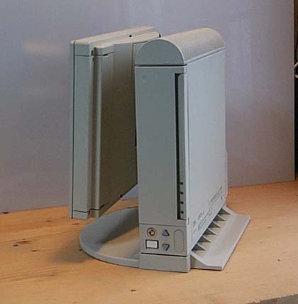
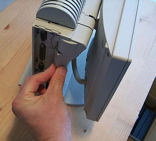
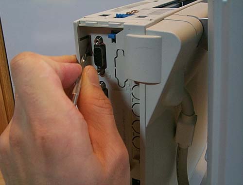
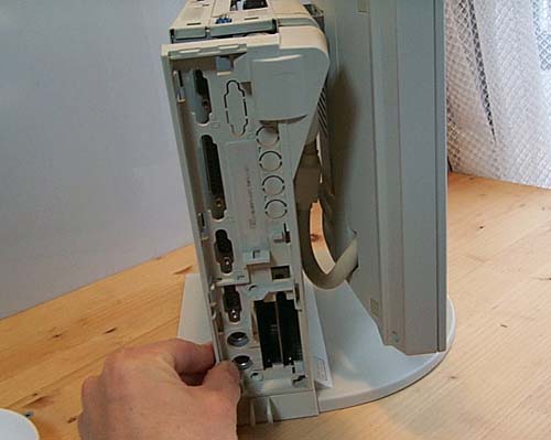
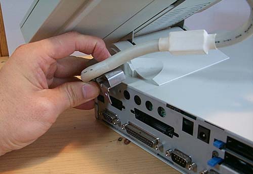
On the left is the PCMCIA slot, AC adapter plug, serial, parallel, and PS2
port.
(missing picture)
The right side has the floppy drive, DRAM socket, power switch, and two
volume buttons.
Opening the Case
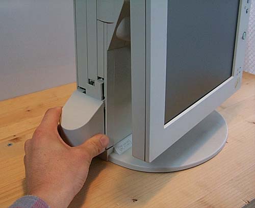
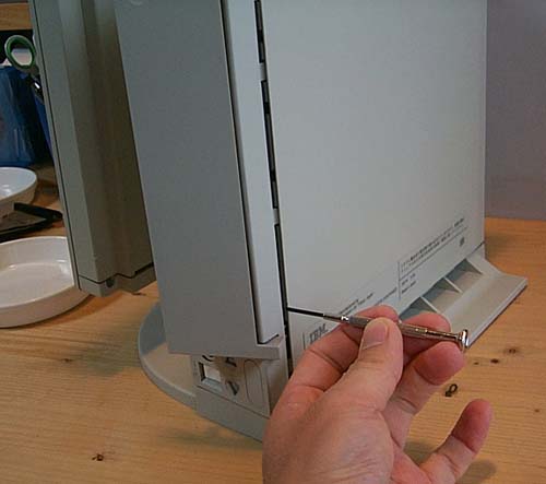
First, remove the accessory covers from the left side of the unit.
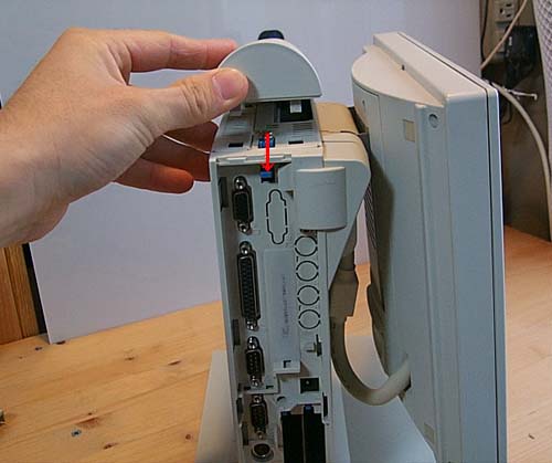
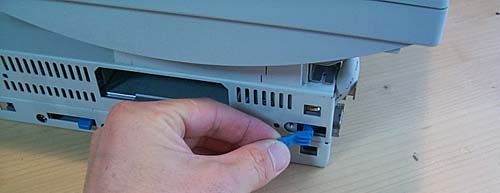
Remove the top cover while lowering the blue lever.
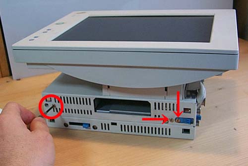
Remove the screw holding the right cover.
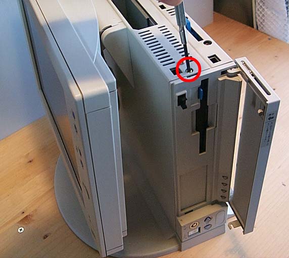
The cover is held in place with a few latches. Pry it off with a
screwdriver.
The cover should come off now.
(missing picture)
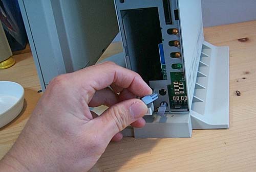
Remove the plastic volume adjustment buttons, so you don't damage or lose
them.
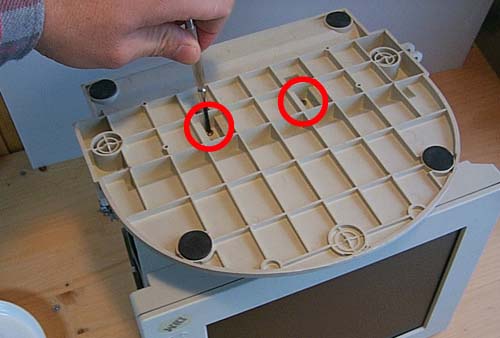
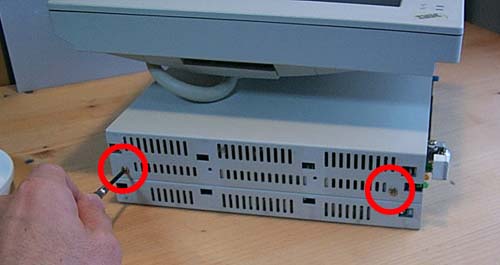
Also remove the screws (long coarse-threaded) that hold the base plate in
place.
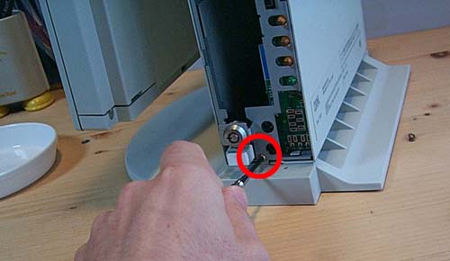
Remove the screw holding the left cover.
It's held in place with a few latches. These can be undone by pushing on
them.
The right cover comes off.
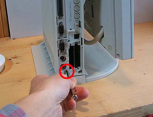
Turn the unit upside down and remove the two screws that hold the stand in
place.
When slid (forward?) it should unlatch and come off the base unit.
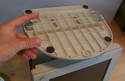
All plastic covers have been removed.
Next remove the two screws that hold the bottom body cover.
Remove the two screws that hold the upper body cover and the screws that
hold the blue lever.
Remove the blue lever.
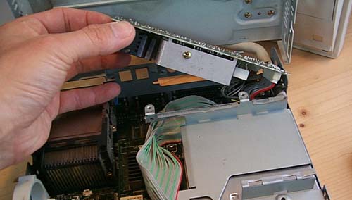
Remove the metal fittings that hold the LCD cable. Tilt the LCD panel for
better access and easier removal.
Lift the main body cover up and pull it out further toward you.
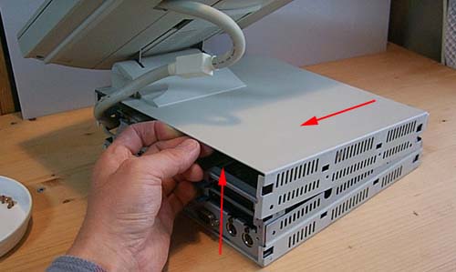
The cover can be removed now.
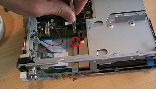
Removing Internal Components
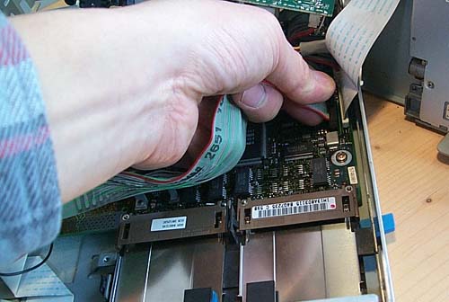
Remove the screw that holds the HDD caddy.
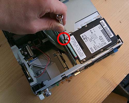
Remove the clip (?) and pull it up.
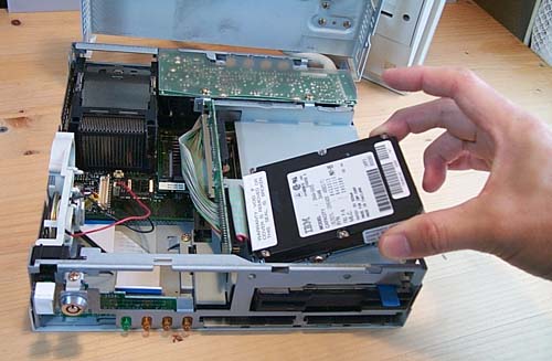
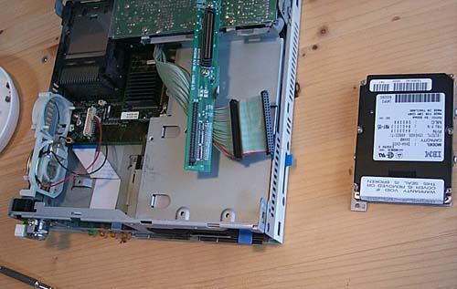
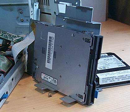
The HDD removed and unpluged from the connector. As you can see the HDD
cable has two connectors of the same type, so you can install two HDDs by
setting one as the master and the other as the slave.
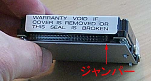
Since the HDD installed in the 5538 is an old type, there is a jumper at the
end of the pin header (when replacing it with the same type, set it as on the
original drive). Normally, the drive is set as a master without a jumper and a
slave with a jumper at the end of the header.
Next we need to access the other end of the IDE cable. Remove the three
screws on the power board.
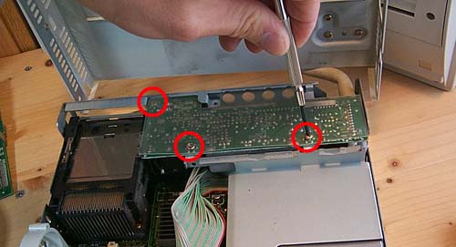
Lift it up and remove it.
To remove the FDD, remove the screw holding the FDD caddy in place.
There are two more screws on the side. Remove them too.
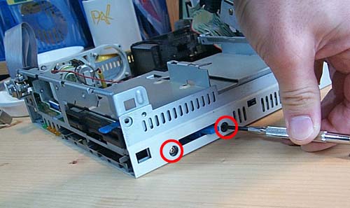
The FDD comes off.
By the way, the FDD seems to be the same type as in ThinkPad 370C and some
other ThinkPad models. (It seems that there are many shared parts, like the HDD
and DRAM card)
If necessary, you can remove the original IDE cable and replace it with a
longer one, or use a 2.5" to 3.5" adapter cable.
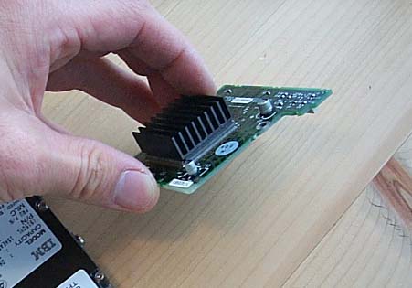
For a reference, here is the CPU card.
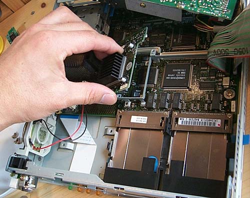
This one is DX4 75MHz.
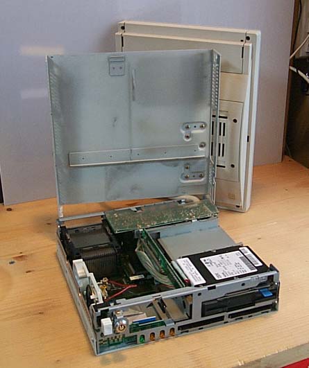
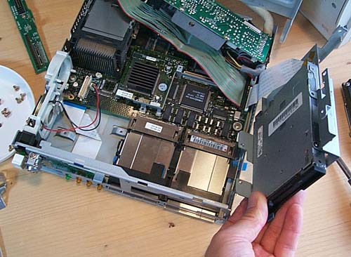
Overview of the inside of the main unit.
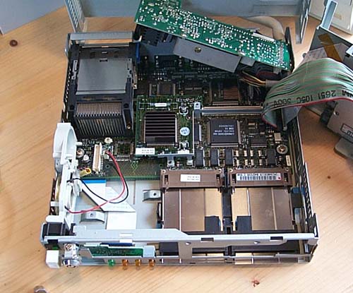
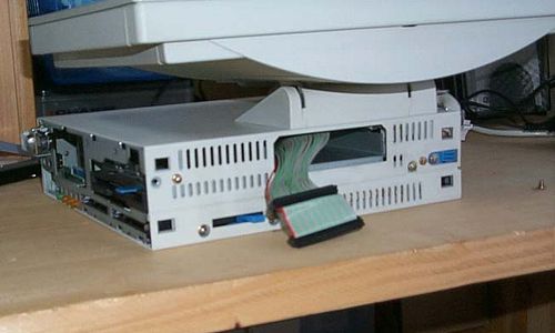
The original IDE cable sticking out of the machine.
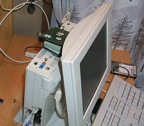
For the time being, I put the HDD on the top, but I'm planning to do it the
right way.
|