|
Specifications
Power Supply Connectors Pinout
Planar Power Connectors P1/P2
Planar Power Connector P9
Planar Power Connector P11 - 3.3 V
Riser Power Connector P10 - 3.3 V
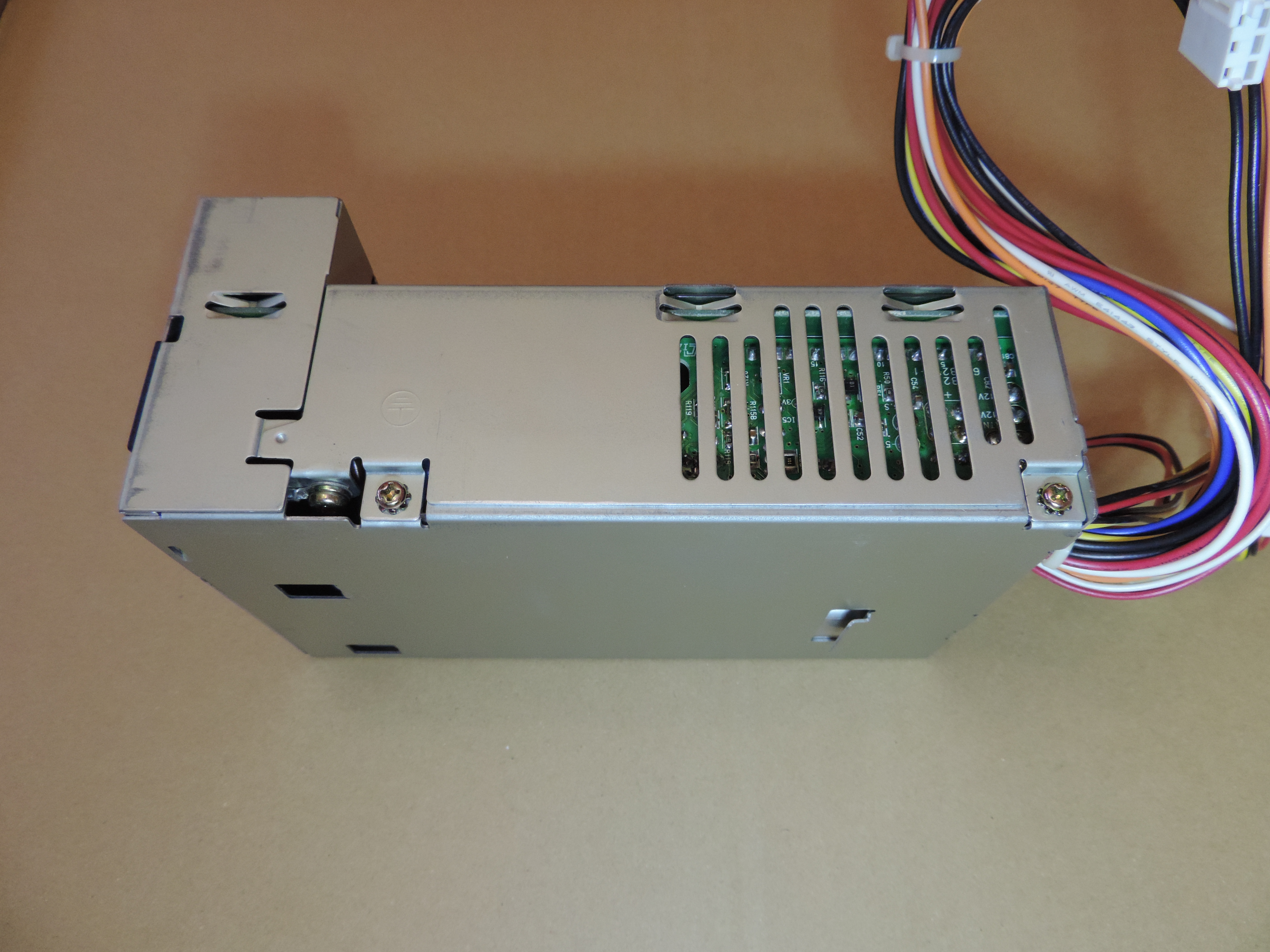
Remove Power Supply
Open Power Supply
Power Supply Inside
Power Supply Fan
Content created by Tomáš Slavotínek and Tatsuo Sunagawa.
Specifications
![[P]](/other/img/photo.gif "Sticker")
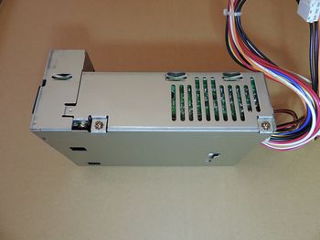
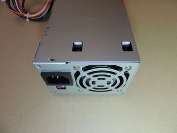
The PC720 power supply is a compact unit with some relatively modern
features. It has a low-voltage power switch (known from later PS/2 and PS/55
machines), a stand-by 5 V supply and a 3.3 V rail. The integrated fan has an
automatic speed regulation.
Power Consumption
Maximum: 70 W
Typical: 40 W
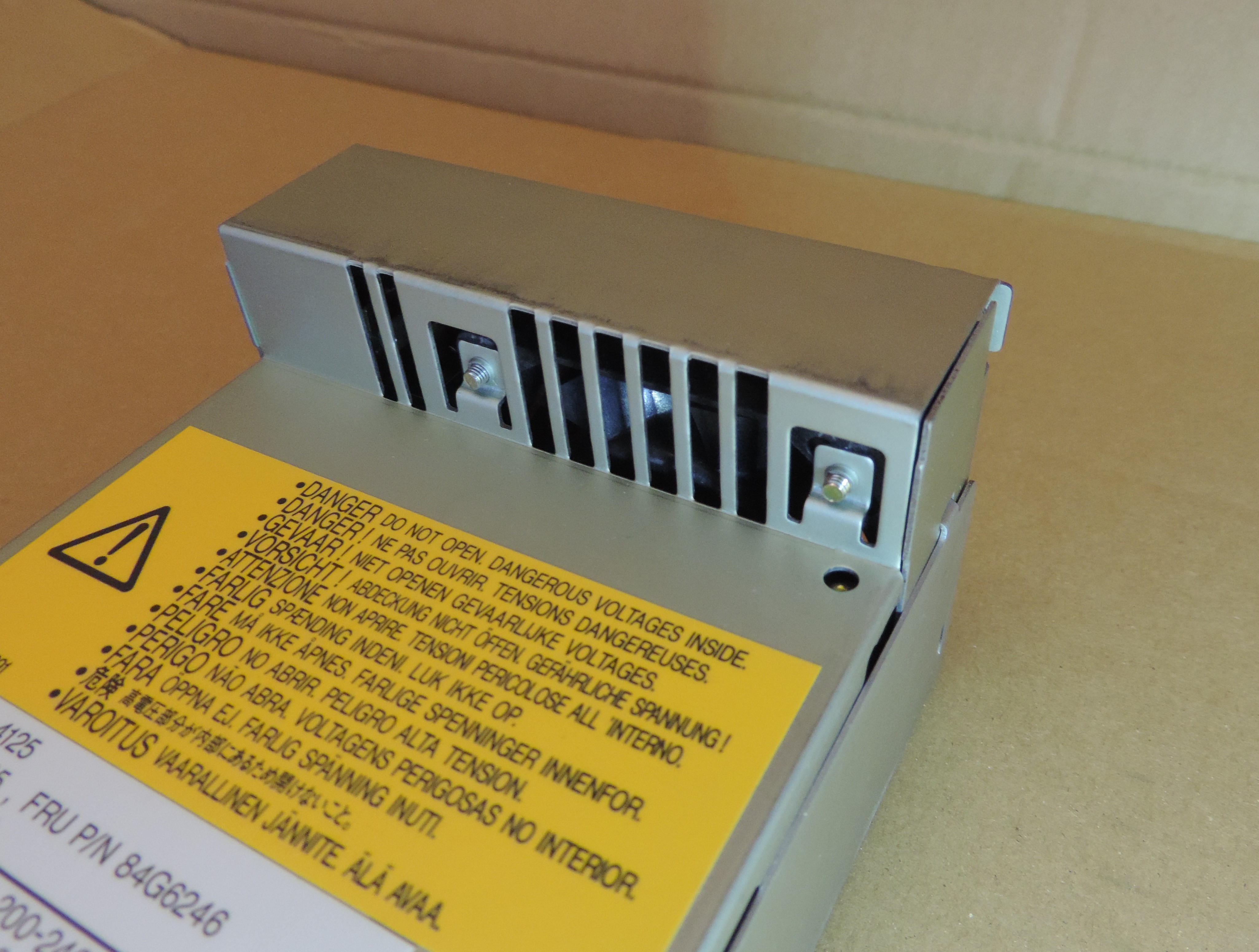
PSU Model
Model NJD-4125
IBM P/N 84G6245
FRU P/N 84G6246
EC NO. D60734
Nagano Japan Radio Co. Ltd.
Made in China
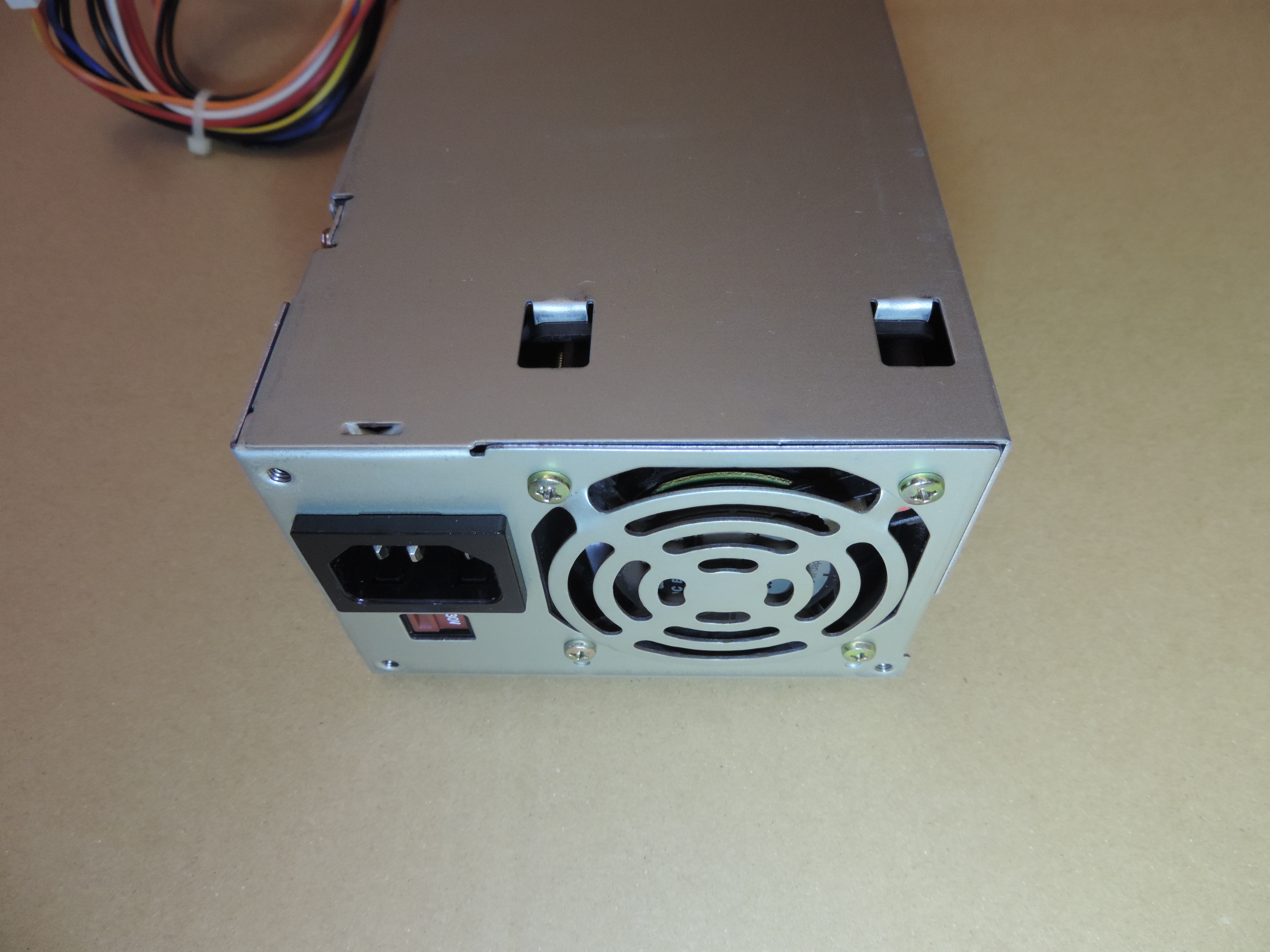
Input
100 - 125 V ~ 1.8 A
200 - 240 V ~ 0.9 A
(manual voltage switch - 115/220 V)
50/60 Hz
Output
+3.3 V @ 4.5 A
+5 V @ 11.5 A
+5 V @ 0.02 A (stand-by?)
-5 V @ 0.2 A
+12 V @ 1.2 A
-12 V @ 0.25 A
Total 57.5 W Max. for +3.3 V and +5 V combined.
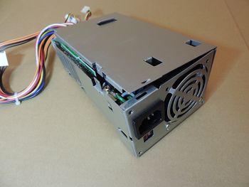
Power Supply Connectors
PSU cabling & connectors (non-modular; permanently attached):
- 4 planar connectors (2x AT style, 1x 3.3 V, 1x SB/PS-ON)
- 1 riser connector (3.3 V)
- 4 drive connectors on 2 separate leads (2x Molex and 1x Molex + 1x Berg)
P1, P2, P10 & P11 are Molex 90331 plug w/ Molex 08-50-0276 contacts.
Power Supply Pinout
Planar Power Connectors P1/P2
| |
Pin(s) |
Description |
Notes |
| |
P1-5,6; P2-1,2 |
Ground |
|
| |
P1-2; P2-4,5,6 |
+5 V DC |
|
| |
P1-3 |
+12 V DC |
|
| |
P1-4 |
-12 V DC |
|
| |
P2-3 |
-5 V DC |
|
| |
P1-1 |
Power Good |
+5 V if all voltages are stabilized |
The P1/P2 connectors use the "standard" PC AT PSU pinout.
Planar Power Connector P9

| |
Pin(s) |
Description |
Notes |
| |
P9-3 |
Ground |
|
| |
P9-1 |
+5 V SB |
Stand-by +5 V supply |
| |
P9-2 |
Power ON/OFF |
OFF: +5 V, ON: Shorted to GND |
Planar Power Connector P11 - 3.3 V
| |
Pin(s) |
Description |
| |
P11-4,5,6 |
Ground |
| |
P11-1,2,3 |
+3.3 V |
Supplies power to the CPU socket (when set to 3.3 V) and possibly some other
minor components (U18 is a 5 V part but one? pin is connected to 3.3 V too).
Riser Power Connector P10 - 3.3 V
| |
Pin(s) |
Description |
| |
P10-4,5,6 |
Ground |
| |
P10-1,2,3 |
+3.3 V |
Supplies power to the PCI slot and the PCI-MCA bridge (U8 - 10G7808).
Remove Power Supply
- Undo the two large flat-head screws holding the top cover of the machine.
Remove the cover by sliding it back and then pulling up.
- Undo the phillips screw (black pan) holding the ISA-like PCMCIA adapter.
Slide the PCMICA adapter out of its slot and remove it.
- Unplug all power connectors from the planar (four), riser (one), and drives
(up to four).
- Unplug the IDE data cable from the hard drive.
- Undo the phillips screw (black pan) holding the hard drive mount and swing
it up and towards the back of the machine to remove it.
- Remove the optional CD-ROM drive and anything else installed in the drive
bays that might prevent the PSU from being slid forward (see the next
step).
- Undo the two phillips screws (black pan) holding the PSU to the back of
the chassis. Slide the PSU towards the front of the machine and then pull up to
remove it.
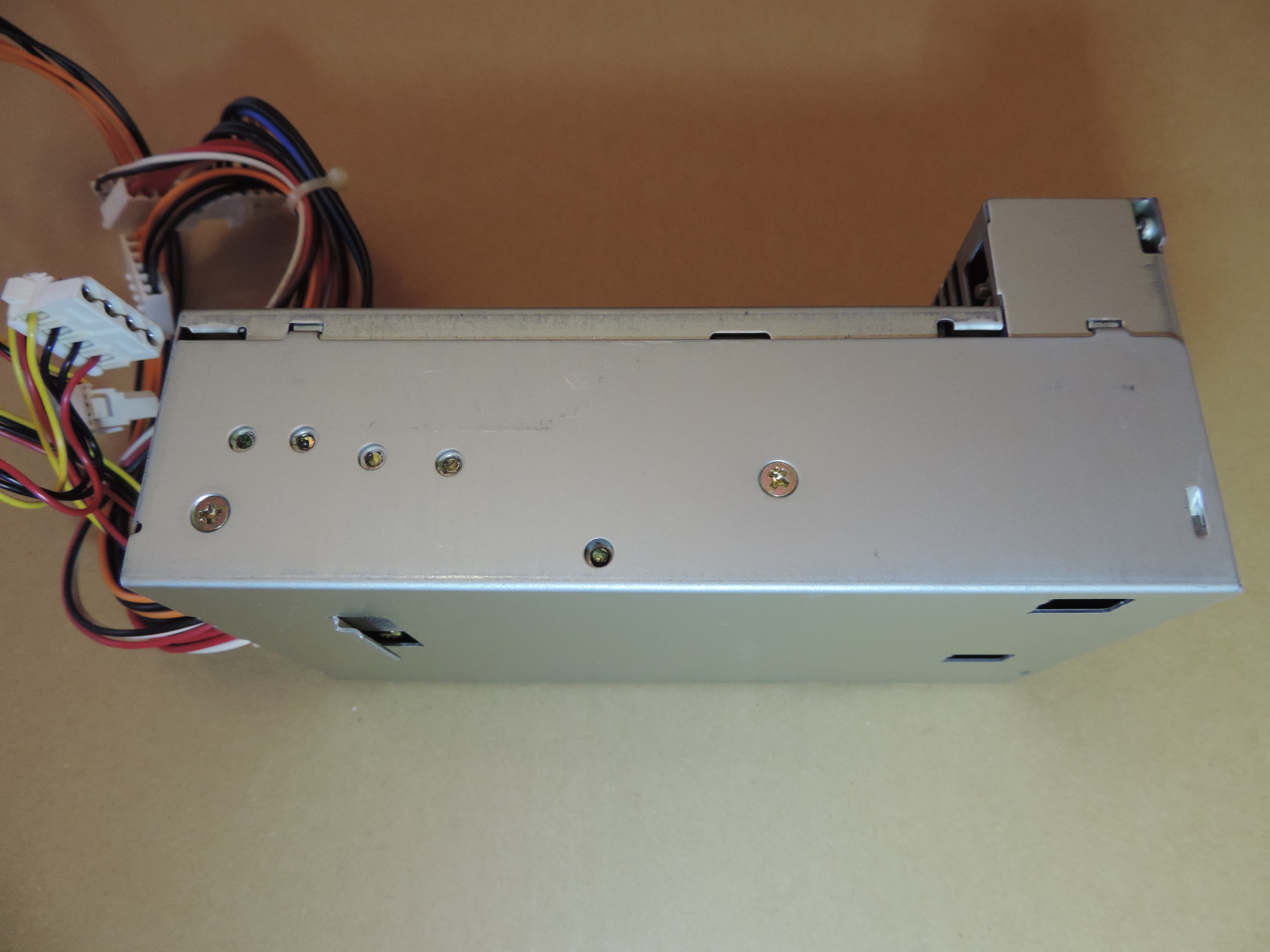
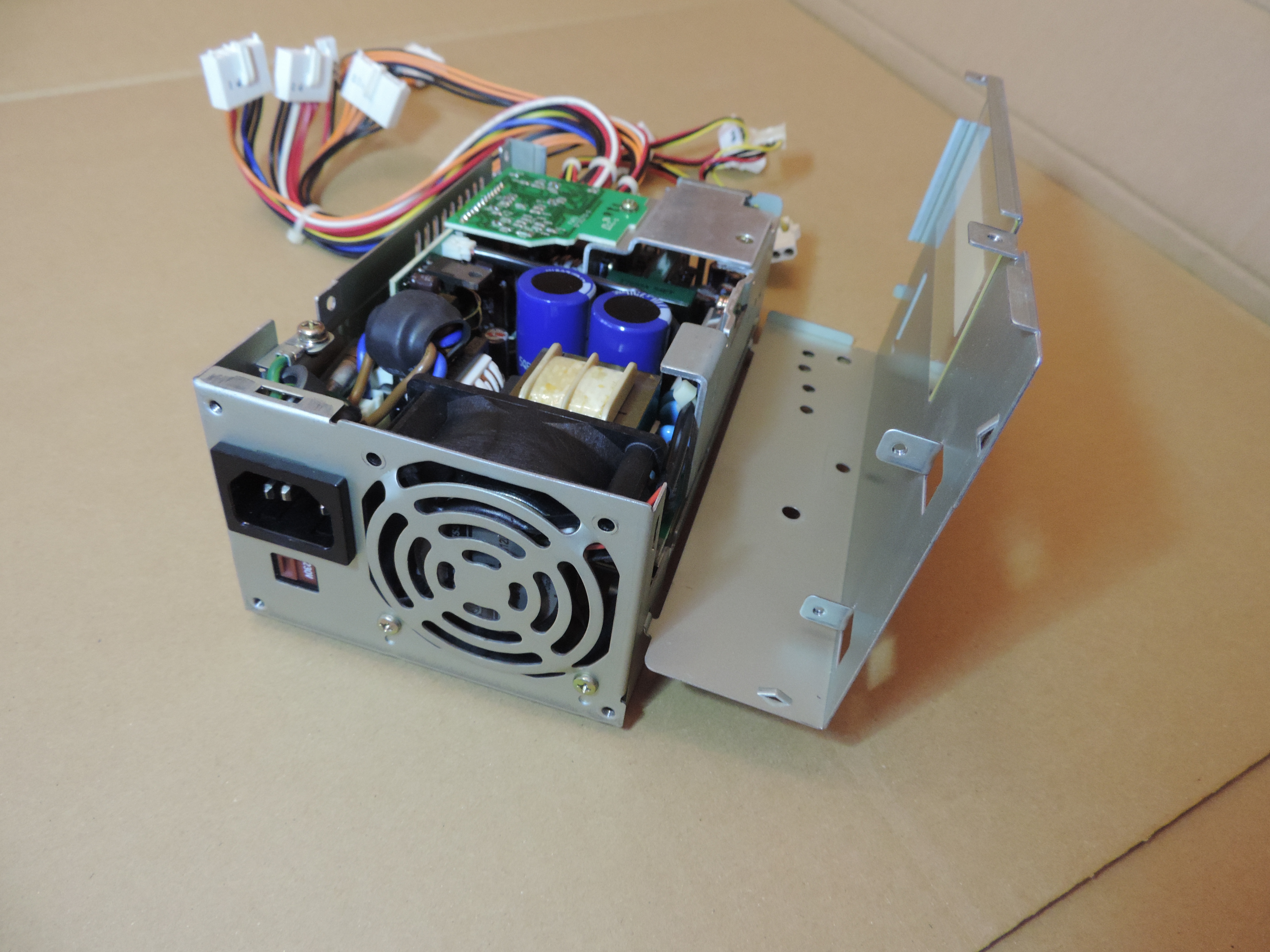
Open Power Supply
- Remove two phillips screws (flat) on the side with no vents.

- Remove two phillips screws (pan) on the other side of the PSU.
- Remove the two bottom phillips screws (top on the picture below) holding
the fan. The screws are quite long and go through both parts of the chassis.
Leave the other two fan screws in place.
- Crack open the bottom cover on the side where the vent is (use a flat-head
screwdriver or some other tool if you have trouble separating the two
parts).
- Hinge open the bottom cover and remove it (the "hinges" are on the side with
no vents).

Power Supply Inside
The PSU consists of one main board with two smaller PCBs plug into each
other.
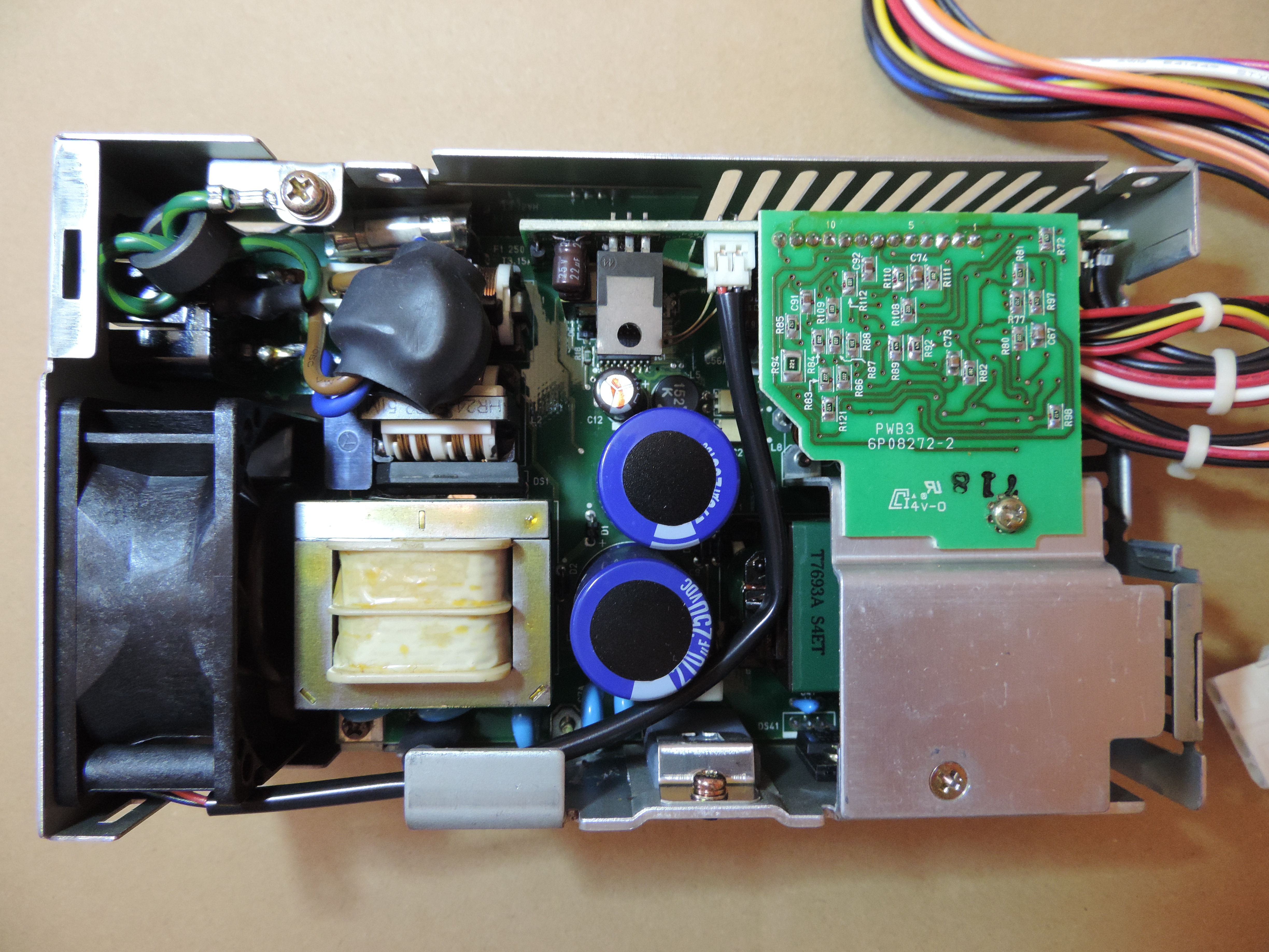
The fuse is 250 V, T3, 15 A with leads and is soldered in.
Power Supply Fan
The rear portion of the PSU where the fan is enclosed is
taller than the rest of the unit. The fan
pulls air not only through the PSU but also around the hard drive that is
normally installed right above. The fan will slow down if the total system
power consumption is lower than 50 W, and will stop to spinning completely if
below 30 W. Thus the cooling fan usually stays idle.
Fan Model
Panaflo
DC Brushless
4L17CN
Model FBA06A12L
DC12V 0.14A
Matsushita Electric
Made in Japan
Specifications (datasheet)
Model: FBA06A12L1A
Nominal speed: 3200 RPM
Max.air flow: 0.40 m3/min, 14.1 CFM
Max. air pressure: 3.10 mmH20, 30.4 Pa
Noise: 24.0 dB-A
Dimensions: 60.0 x 60.0 x 25.5 mm
Fan Speed Control
Sandy's experience and fan modification (edited):
When I got the 6860 I've immediately noticed that the fan wasn't
running at all. As I didn't know about this unique feature I thought there must
be some fault on the circuit board of the PSU. I disassembled PSU and soldered
12V line directly to the fan assembly. Only latter on have I learned about this
unique function. The jumper wire is still there... Some machines have input AC
voltage selector. Mine has a "fan mode selector", summer mode with direct
connection and winter mode with original connection.
The machine works fine under DOS. But under Win95B it usually freeze at
start up after the Win95 logo appears on the screen. I solved this symptom by
modifying MSDOS.SYS to have a start up menu with default boot for Win95 after
60 seconds of delay time to boot. Maybe mine needs some delay for stable DC
output for planar, a hard drive and a CD-ROM. I'm sure that this symptom is not
related to the above mentioned fan cable modification, 'cause I have the same
problem even when I switch back to the original cable connection.
| 
