|
Disclaimer
Opening the 400 W PSU
Security Torx
Security Phillips
Remove Screws in Rear Wall
Removing AMP Planar Power Socket Retainer
PSU Rear Wall Catches
Remove Inner Wall from Case Slots
Thoughts on Factory PSU Assembly
PCB Guides
Horizontal PCB Guides
95A Power Supply Exposed!
Power Supply AC Socket
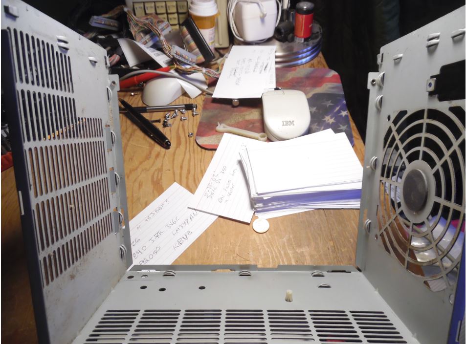
Fan
PSU Fan Connector
Fan Cushion
Fan Control PCB
2 Pin Fan Connector
Fuse
Reassembling PSU Knob Shaft Well
Inserting Rear Wall
Disclaimer
I opened up my 95A 400 W power supply. I do NOT
advise anyone to attempt to fix or modify the power supply. I take NO responsibility for what you do! You are doing this on
your own!
This page is ONLY to expose you to the quality
construction used on the 85/95 series systems! I have left many details out,
because I'd rather not have people opening these power supplies. They have
pretty big capacitors in there. Seen bigger, but these will hold a sufficient
charge to ruin your day.
In no way do I suggest that you try this! I don't have safety tips for the
proper de-energizing of the circuitry for power supplies that have been used
recently. I used a power supply that hadn't been powered up for over six
months.
Warning! Assume all heatsinks to be live when the
power supply is plugged in!
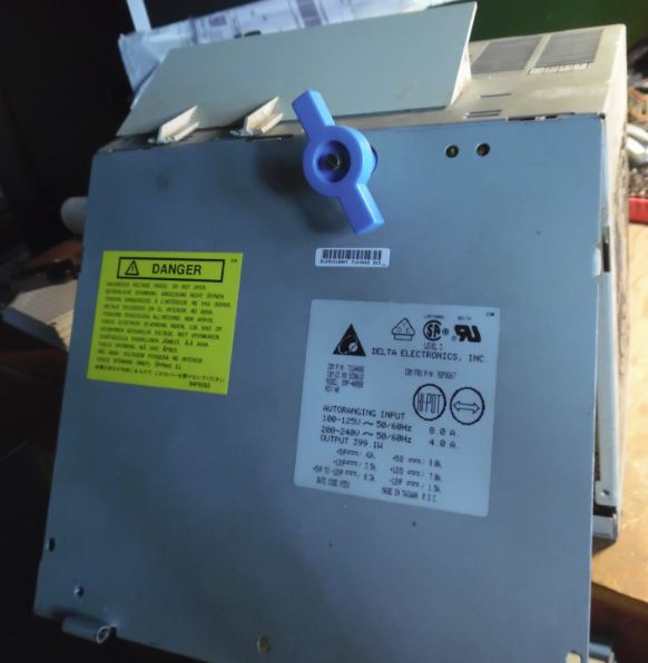
Opening the 400 W PSU (Delta model SMP-400BP, others similar)
Here are the tools and procedures for a (relatively) painless way to open a
PSU to clean it. I do not have any schematics for this or any other PS/2.
Everything here is either scoured from the internet or a result of (usually
painful) personal experience.
Security Torx
Menards had the Truecraft model #6232 32 Piece Bit & Socket Magnetic
Ratcheting Driver Sets (about $20). It has tamper proof T10-T40 Torx bits. The
bits and case are Taiwanese and the ratchet and sockets are US. The bits are
heat treated S2 steel (good stuff). You need the security T-15 bit.
Craftsman has a set of security bits and magnetic handle for @ $27, BUT it
has the security Pillips, Torx, spanner, and others. Nice and compact.
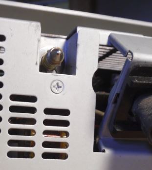
Security Phillips
To take off the inner side panel, you WILL need a security TP2 Phillips. The
95A PS uses a stamped metal "well" to fully surround the PS knob's threaded
end. This well is fastened to the top of the case, as well as to the side panel
by the security Phillips.
I made my "security Phillips" screwdriver with a cheap old Phillips. Threw
it into a vise and hacksawed two slots at right angles to the edges. It has
four separate points sticking up around the center now. I would get a real
security Phillips if I was doing this a lot. It worked but I would not want to
really torque on it.
Removing the PS Knob Shaft
(only needed for total PSU teardown)
Push the knob in so the e-clip on the inner side is accessible. Use needle
nose pliers or a standard screwdriver to remove it.
Note: With 400 W PSUs, the air deflector on the
top edge interferes with removing the top, on later 400 W PSUs the front and
rear sides are tack welded to the front and top walls. In this case, just drop
the inner wall of the PSU. You only need to drop the Phillips screw below the
PSU knob (the top Phillips can remain installed).
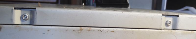
Remove Screws in Rear Wall
To remove the PSU rear wall, you need to remove the TP2 Phillips just below
the PSU fastening screw. You can leave the top TP2 alone, and leave the PSU
Knob right where it is. It does not pass through any PCBs.
Remove Bottom Inner Edge Screws
Place PSU on it's outer side. Whip out your T15 Security Torx and remove
both screws.
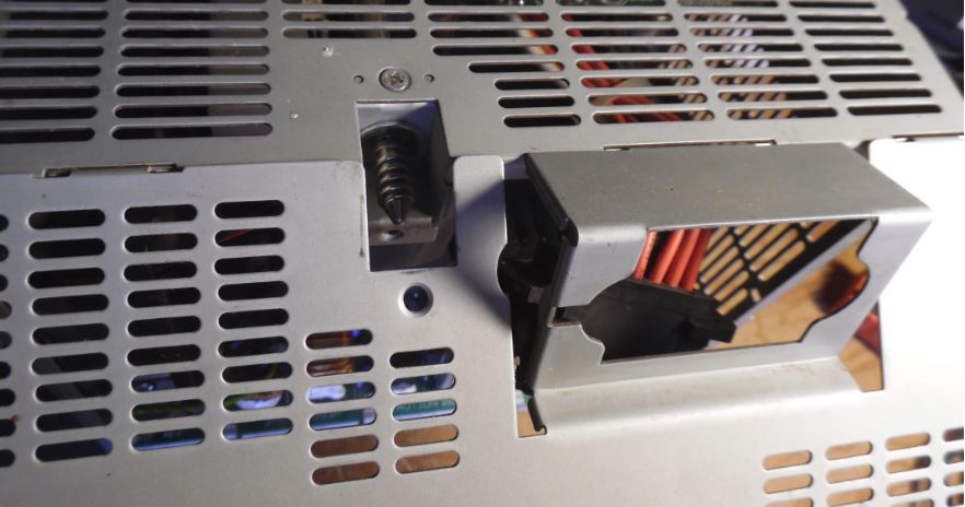
Removing the Planar Power Socket
If you want to unmount the AMP planar power socket, you will need a small,
thin bladed standard screwdriver. The retaining collar has two pairs of hooks
on each side of the power socket. With the PSU laying on the outer side, look
under the metal angle that the Planar Socket is mounted on.
See the hooks holding on the bottom of the socket? While pulling up on the
collar, pry the hooks away from the socket, one end on one side, then the other
end. Move to the other side and work off the hooks again one at a time.
PSU Rear Wall Catches
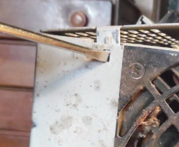
Remove Inner Wall from Case Slots
Once all screws and the planar power connector are removed, and the Inner
Wall is freed from the rear PSU case wall, then turn your attention to the top
inner edge. There are three tabs from the top of the inner PSU case wall that
slot into the top PSU case wall.
I ended up flexing the inner wall up and down while pulling out and up at
roughly 45 degrees.
Images to come when I open one of my last, extra 400 W PSUs.
Thoughts on Factory PSU Assembly
Looking at the shell, it seems that the air deflector was put on last.
The front wall has tabs that fit onto slots in the top wall of the PSU. Like
the back wall, but in front... The air deflector has two alignment tabs that
extend over the front wall of the case, but those tabs are not connected with
adhesive.
My guess - air deflector was applied to finished PSUs, and any adhesive is
under "lean-to".
For visualization of the case, the front, top, and rear walls are an
inverted "U". The inner wall is a separate piece. The front wall and the bottom
wall form an "L".
From my perils of pulling this 400 apart, if you want to fully disassemble
one, you need to remove the two air deflector "tabs" that hang over the front
wall of the PSU.
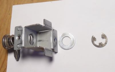
Disassembled Well Parts
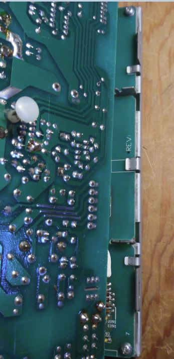
PCB Guides
This is the inverted "U", front, top, and rear wall of the PSU. Note the PCB
guides along the outer edge of the PSU.
Notice the metal clip at each lower end of the "U" (case upside down, clips
at upper ends of "U"). These clips hold the horizontal PCB's bracket. The way
this is laid out, it appears the inverted "U" slides down over the vertical
PCB.
Note the PCB guides for the horizontal PCB. The single double guide at the
middle of each end (front and rear) allows the horizontal PCB to be pushed over
the double guide and slide forward to engage the case clips.
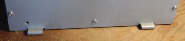
Vertical and Horizontal PCB Bracket
This shows the vertical PCB bracket cut-outs, and how the clips fit over the
vertical PCB. Also see the "U"s where the horizontal PCB slides in.
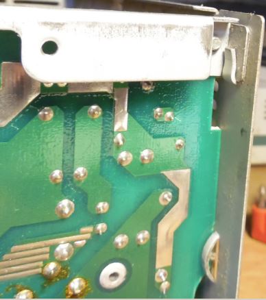
Vertical PCB Bracket Clips
The bracket on the vertical PCB hooks under the clips at the front and rear
of the "U". Note the threaded hole for one of the two T15 Torx screws holding
the front wall on.
Vertical PCB Bracket Screw
The vertical PCB Bracket is fastened dead center with a T15 Torx.
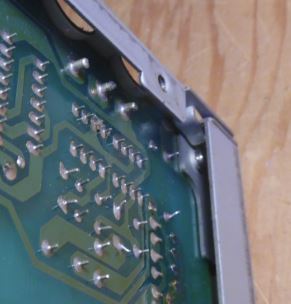
Horizontal PCB Guides
See the way that the corner of the bracket is secured by the clips at the
corner? Also, note the double guide near the bottom right of the picture. There
is a semi-circular cut-out that the PCB clears when being assembled, and once
the PCB reaches the single PCB guides, the horizontal PCB is pushed to the
outside wall, and the corner clips and the center double PCB guide are
engaged.
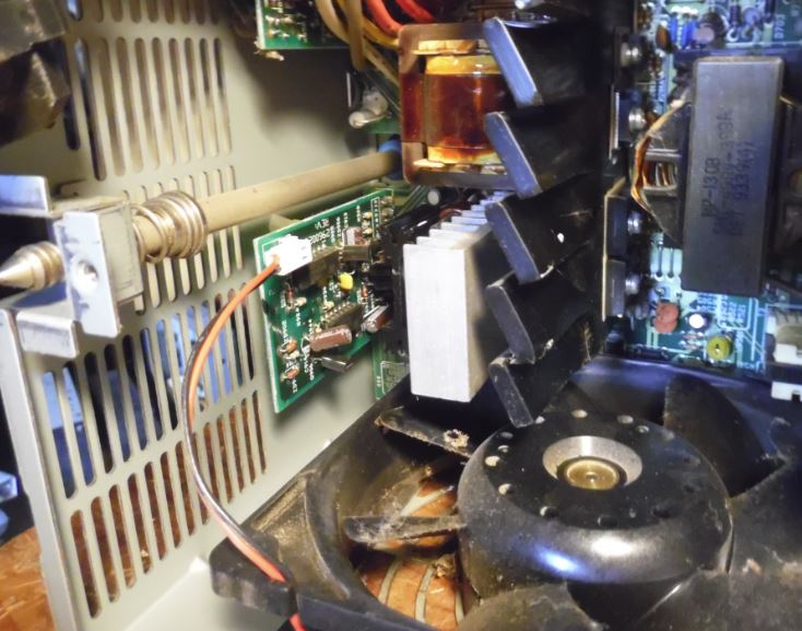
Oh My God! 95A Power Supply Exposed!
This is NOT a clone power supply! The main heatsink is 3" high, 3/16th"
thick and 7" long! The conductors coming off the main circuit board are 14AWG,
600V, 105°C rated. For those not techno-savvy, that means you could safely run
115V/15A on these conductors! The 105 rating is WAY above some common power
supplies I've looked at. The fan is removed in this image.
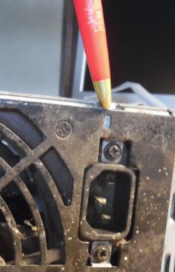
95A Power Supply AC Socket
It has an EMI filter, rated 115/250 V, 10 A at 50/60 Hz, 40 °C.
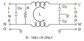
Cx .1uF
R not in this model (no "-R" suffix)
L 0.2mH (image on socket has no "L", possible one on L, one on N?)
Cy 2200pF
Delta 10GEEW3E, 10A 115/230 volts. Mfr 9337 by Delta
(datasheet).
Fan
At this point, the "109R" model is close enough.
Burnout protection function at locked rotor condition
Current cutoff system - If the fan blades are restricted, the coil current
is cut off at regular cycles to prevent overheating of the coil. When the
hindrance is removed, the fan restarts automatically.
Reverse polarity protection function
No problem about fan even if positive & negative lead are connected in
reverse. (However, when wiring fans with sensors or PWM speed control function,
connecting positive and negative leads in reverse may damage the fans.)
Note: Both the 329 W and 400 W fans do NOT have
sensors, and the fan does NOT have PWM circuitry inside it.
329 W PSU Fan
Model 109P1212H402
DC12V 0.45A - 5.4W
Seven "squarish" blade, ribbed, uses through hole screws with nuts on inner side of PSU.
12 V, 0.45 A, 5.4 W, 2,800 RPM, 2.5 m3/min (88.2 CFM), 53.9 Pa, 40 dB
109P1212H402 page
Datasheet
109P - Plastics
12 - 120×120mm
12 - 12V
H - 2800 RPM
4 - 25mm thick
02 - Without a sensor
Lacks 13th position, it uses a ribbed impeller body.
400 W PSU Fan
Model 109P1212H1021
DC12V 0.52A - 6.24W
Seven "rounded" blades, ribless, uses metal clips for mounting screws
109P - Plastics
12 - 120×120mm
12 - 12V
H -2600 RPM
1 - 38mm thick
02 - Without a sensor
1 - Plastics frame: Ribless frame (13th position)
109R1212H102(1021) Datasheet
12 V, 0.52 A, 6.24 W, 2,600 RPM, 2.9 m3/min (102.3 CFM), 64.7 Pa (0.260" H2O), 39 dB
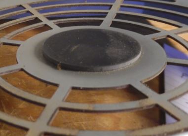
Fan with sticker removed
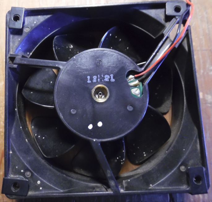
Once you carefully peel off the round black sticker from the back of the
fan, you will see it has three contacts (only 12V and GND used) and the lone
identifier, "12H21".
See the small fan spindle in the well. A SMALL e-clip holds the fan in the
hub.
Sanyo Denki Co. DC San Ace Brushless
PSU Fan Connector
Looks to be PWM on the fan control PCB.
After cracking open the oyster, you might be able to oil the bearing with
the fan in the case.
Remove the inner wall. Place the PSU with the fan exhaust pointing DOWN.
Sparingly oil the bronze center of the fan. Spin it slowly with your fingertips
until the oil seeps into the bearings. This is a tight fit, so it might take a
while.
Fan Cushion
I finally noticed this while re-assembling my sick 400 watt PSU. The fan hub
is pulled onto this when the mounting screws are tightened. Vibration
control?
Fan Control PCB
The fan control PCB has two LM339N op amps on it, a few signal(?)
transistors, and a few caps. Unless I destroy this (non-working) PSU I can't be
totally sure of what is on the controller, but from the looks of it, ain't
nothing special.
LM339N - Low-Power Low-Offset Voltage Quad Comparators. With two, I bet you
can make a PWM DC motor controller...
This Fan Control might monitor both fan voltage drop and PSU output voltage
drop.
The fan itself has two wires, so no tach or temperature input to the fan
control. No visible temp control found yet on the PCBs (might be there, but not
on Fan Control).
Think about it, you can't just monitor fan speed without monitoring PSU
load. Monitoring current vice voltage drop takes higher rated components
because current measuring device must be in series and must be able to handle
amperage.
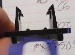
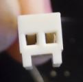
2 Pin Fan Connector
Molex 5051 Series Headers & Wire Housings - hooray!
2-pin white connector marked MXT 29 5051:
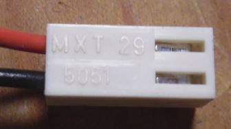
For the fan wires:
2.50mm Pitch KK® Wire-to-Board Housing, Female, Friction Lock,
for 2759/5159 Crimp Terminals, 2 Circuits
Part Number: 22-01-1022
Engineering/Old PN:5051-02
2-pin Header on Fan Control PCB marked "MXT B (or "8", cramped space) 5046:
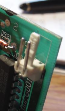
For the Fan control PCB header:
Mini-Latch™ Wire-to-Board Header, Right Angle, Friction Lock, 2 Circuits, Tin (Sn) Plating
Part Number: 22-05-1022
Engineering/Old PN:5046-02A
Pins look to be .66mm / .0025"
KK® Cat Ear Crimp Terminal 5159, 22-28 AWG
Engineering/Old PN: 5159
Phosphor Bronze, Tin (Sn) Plating or Brass, Tin (Sn) over Copper Plating
24AWG, Type TR-64 AWM VW-1 1007 E44013, wires say "DENKO" and "DAIICHI"
Dai-Ichi made the small gauge wires for DC fan manufacturers.
PSU Fuse
1⁄4” x 1 1⁄4” ABC Series, Fast-Acting, Ceramic
Tube ABC-8 Datasheet
T8AH 250V. If this fuse blows, remove the short circuit from the output.
Though if this has blown, something is wrong because the power supply should
have shut down by itself! If the fuse blows again after removing a shorted
output, I recommend you take a power supply to a real electronics repair
tech.
Reassembling PSU Knob Shaft Well
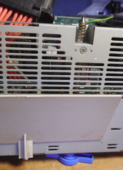
After fastening top of well to the top side of the PSU, pass the PSU Knob
Shaft through the hole in the well. Now put the PSU on it's side. This makes
applying compression to the PSU Knob easy.
Installing E-clip
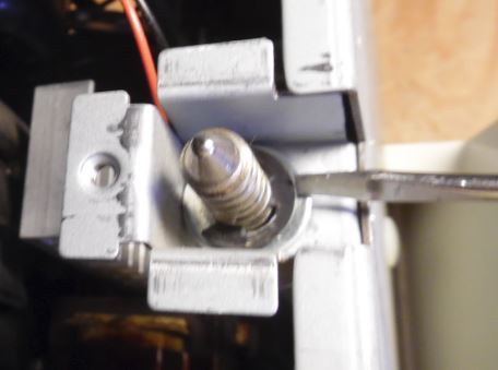
With the PSU resting on the blue knob, it is much simpler to keep the shaft
at the proper protrusion. Place the e-clip so the outer ends fit into the
groove and use a standard screwdriver to push the clip onto the shaft.
Inserting Rear Wall
The rear wall tabs fit into the slots in the top wall.
|