|
8600 Power (Todd Products MAX-753-0512)
MAX 700/750 Series
Datasheet
MAX-754 Series Datasheet
(Replacement)
I do not have a complete list of Todd MAX-70x/75x and
NMX- supply models. Others may be compatible, but I
can't prove it. One plus is that the case fan is
connected to leads on TB2, so you can swap a fan-cover
onto a suitable replacement PSU...
750 watt universal power supply; Optional
redundant power supply.
Note: The PSU is
Universal, but NOT Auto-Ranging. There is a set of spade
terminals on the PSU's PCB, connected for 115v, open for
230v.
Replacements for MAX-753-0512
MAX-753-0512
----> MAX-754-1205P Replacement has extra
output and feature (P option) customer doesn't need to
use.
MAX-754-1205P has an NSN of 6130-01-487-6246.
Unfortunately, all I see is "RFQ" for price. Spidey
sense makes me think that it isn't cheap...
Some Wild
Guesses
Chances are the PCBs for the MAX 70x and 75x series are
the same, but the components installed will change. That
is why I'm looking to detail the inputs, configuration
points, and outputs. All we need is close enough.
| MAX |
Watts |
Output #1 |
Output #2 |
Output #3 |
Output #4 |
| 703-0512 |
700 |
+5V @ 100A |
+12V @ 12/20A |
-12V @ 10A |
|
| 704-1205 |
700 |
+5V @ 100A |
+12V @ 12/20A |
-12V @ 10A |
5.2V @ 2A |
| 753-0512 |
750 |
+5V @ 120A |
+12V @ 12/20A |
-12V @ 10A |
|
| 754-1205 |
750 |
+5V @ 120A |
+12V @ 12/20A |
-12V @ 10A |
5.2V @ 2A |
| 754-1212 |
750 |
+5V @ 120A |
+12V @ 12/20A |
-12V @ 10A |
12V @ 2A |
| 754-1224 |
750 |
+5V @ 120A |
+12V @ 12/20A |
-12V @ 10A |
+24V @ 2A |
| 754-1252 |
750 |
+5V @ 120A |
+12V @ 12/20A |
-5.2V @ 10A |
12V @ 2A |
Note: The MAX-70x
models Output #1 is +5V @ 100A,
useable BUT will support less MCA adapters or hard
drives or memory. Only a 100w difference, so if you
are thoughtful, it should work.
Note: All Output #2
outputs have a sustained / peak rating of 12A / 20A.
(peak) refers to a momentary surge, say
for starting drives. Inrush current. So, +12v at 12A
sustained, +12v at 20A for a short period...
Caution!
MAX-754-1252 Output #3 is -5.2V @ 10A, NOT -12v!!! Will
not function as a replacement...
MAX-753-0512 Fan
USTF922512LW
USTF9225 Series DC Brushless Fans
| Model |
Volts |
Watts |
Amps |
RPM |
dB |
CFM |
| USTF922512LW |
12VDC |
0.84 |
0.07 |
2100 |
25.0 |
37.1 |
25.4mm thick, 92mm square
MAX-753-0512 Terminals
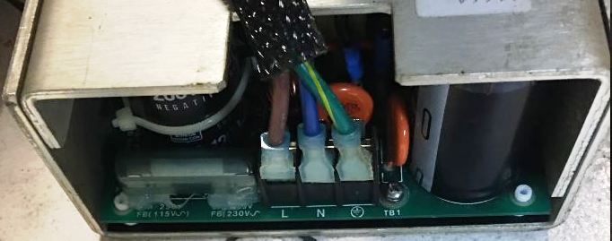
TB1
Terminals (AC
Input)
| Function |
115 Vac |
230 Vac |
Color |
| Input Select |
Short |
Open |
N/A |
| TB1 - (L) |
Line |
Line 1 |
Brown |
| TB1 - (N) |
Neutral |
Line 2 |
Blue |
| TB1 – (⏚) |
Ground |
Ground |
Green |
Note: inputs TB1-3
use a Barrier strip with #6-32 screws on 3/8" centers
Lorenzo Mollicone says:
When the inside power switch is closed, the
main power is off. When the inside power switch is
open, the computer powers up. Without the
switch connected, the machine powers on with the
main power switch located above the power connector.
Input Select: pair
of 1/4" spade terminals mounted on PCB, up from TB1
underneath the cover. For 115v, connect with a short
wire with female spade connectors, or for 230v, leave
the terminals bare (open).
Note: The Input
Select jumper wire is a heavier gage. Checking.
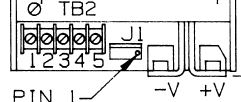
TB2 Terminals (DC Output)
| Function |
Location |
Notes |
Color |
| Output #1 |
Terminal +V |
Main Output |
Yellow? |
| Terminal -V |
Rtn (Common) |
Black? |
| Output #2 |
TB2-3 |
|
Yellow |
| TB2-4 |
Rtn (Common) |
Black |
| Output #3 |
TB2-5 |
|
Blue |
| TB2-4 |
Rtn (Common) |
Black |
| Output #4*(If provided) |
TB2-1 |
(+) |
N/C |
| TB2-2 |
(-) |
N/C |
Note: Output #1 (-V
and +V) is connected with Bus bars using #1/4-20 screws
Note: Outputs # 2-4
use a Barrier strip with #6-32 screws on 3/8” centers
Note: Cover fan
connects to TB2. Fan Black goes to TB2-5, Fan Red goes to
TB2-4.
J1 Terminals (Status and Control), That
little plastic 4 position plug to the right of TB2. Pin
numbering is reverse of TB2, Pin 1 on right, pin 4 on
left. Go figure...
| Function |
Location |
Notes |
Color |
| Remote Sense |
J1-1(+ S) |
Output #1 Sense |
Red |
| Remote Sense |
J1-2 (– S) |
Output #1 Sense Rtn |
Blue |
| AC Power Fail, or DC Power
Good* |
J1-3 (PF) |
Reference to J1-2 |
N/A |
| Inhibit |
J1-4 (IH) |
Short to J1-2 |
Brown |
J1 Connector AMP MTA
type #640456-4 pin header (locking)
Note: Pin 3 (AC Fail
or DC Good) is not connected (N/C). There is no wire to
Pin 3. If you are replacing the original MAX-753-0512 with
a PSU that has PF, leave the PF unconnected.
MAX-753 Series Specs:
OUTPUT Adjustability: User adjustable ±5% minimum.
Line & Load Reg: ±1% over AC range, 0-100% load
change.
Note: Output
#1 requires min load of 10%.
Ripple & Noise: < 1% p-p or 100 mV, whichever is
greater.
Remote Sense (Output #1): Corrects for 250 mV total line
drop. Open sense lead protection.
Temperature Coefficient: 0.02% per degree C.
Stability: 0.1% over 8 hours after 30 minutes warm-up.
Transient Response (Output #1): Output v returns w/in 1%
< 500 μs for 50% load change. Peak Transient Does not
exceed 5%.
Overload: All outputs overload / short circuit protected.
Auto recovery upon fault removal.
Overvoltage (Output #1): Protects load against power
supply induced overvoltage.
Trip point factory set so output voltage cannot exceed
136% of nominal.
Remote Inhibit: Contact closure to negative sense line
drops output power to nominal
OPTIONS:
Option "A", AC Auto-Range: Automatically selects 115 or
230 Vac range.
Option "F", Fan/Cover Assembly: Cover w/ fan needed for
full ratings at 50°C ambient.
Option "G", DC Power Good: Not present on 295.
Option "P", AC Power Fail: Not present on 295.
|