|
"Short story long" (how it all happened...)
Results (what to expect from this mod)
Parts and equipment needed
How To
Note: Shortly after this tutorial was written,
David Beem checked his 9585 "X", and came up with a
surprising
discovery. The Op Panel logic on the X planar is nearly identical to the
K/N one. And not only that, the Op Panel logic is actually fully populated!
(well, at least on his board)
David tested his machine with the Model 95 Op Panel, and sure
enough, it displays the POST checkpoints out of the box, no modifications
needed. He was also able to confirm the part numbers used in this
tutorial...
Content by Tomáš "Major Tom" Slavotínek.
"Short story long"
While poking inside the 9585 K/N POST/BIOS code I have noticed that it
outputs checkpoint codes to ports 108 - 10Fh. On the higher-end Model 95 this
I/O range is assigned to the Op Panel LED display. The BIOS code in both
machines clearly originates from the same codebase, so I thought that it was
just a leftover.
Later on, when recapping my 85 N planar, I've spotted some unpopulated parts
near the Indicator Panel connector. Interestingly enough, they are not your
obligatory "SP" - "spare" positions. They are very obviously wired to the rest
of the planar, and they even have proper reference designators. Hmm, that sure
is suspicious... My curiosity got the best of me, so I have decided to do some
probing, and sure enough, there are some direct connections between the solder
pads and the Indicator Panel connector. One of the positions - U125 - is
directly wired to pins 3, 5, 7, 9, 11, 13, and 15. These pins are not used by
the original Indicator Panel, and are marked as "Reserved" in the Model 85
Technical Reference. However on the sportier Model 95 Op Panel they are
connected to data pins of the LED display units. Aha! All this can't be just a
coincidence!
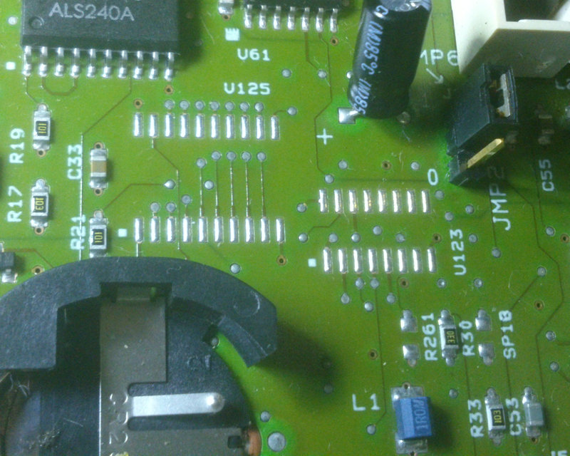
Picture 1: Top side of the board, unpopulated positions
At this point it was pretty obvious to me that IBM designed the planar with
the fancier Op Panel in mind. Maybe all systems were supposed to come with it,
or maybe it was available only on some "special bid" systems for some big
customer. We will probably never know... But that doesn't really matter, let's
try enabling it!
Note: It's safe to assume that they intended to
use the newer version of the Op Panel - the one with HD-activity LED, and power
button on the left side. So we are going to focus on this variant here. (The
older panel may work as well, but some pins that are used here, are tied to
ground on the older version. So proceed with caution...)
So, we know that it should be possible to get it working again by simply
repopulating the missing parts. We also know how the LED display subsystem
works, and that it's very simple by nature. Therefore it's unlikely that we are
lacking some custom or programmable parts, the missing stuff will be just some
74xx glue logic and perhaps some passives. We however don't know what exactly
the missing parts are supposed to be, and if all of them are actually related
to the Op Panel. We can answer some of these questions by analyzing the circuit
and by comparing it to the 8595/9595 planars.
The LED display needs 4 "ingredients" to operate:
- power
- address (character position)
- the write enable signal (which LED unit should be accessed?)
- and the actual data (ASCII code of the character)
Since the Op Panel and Indicator Panel share the same basic pinout, we don't
have to worry about frying anything, and the first ingredience - power - is
already covered. We can confirm this by measuring voltage on the power pins of
the LED units, or simply by watching the LED displays flash briefly when you
power the system unit off.
We have previously discovered that the data lines are going to the
unpopulated position U125. There we expect to see some sort of line drivers or
transcievers that would sit between the planar I/O data bus and the LED units
themselves. Layout of the solder pads reveals to us the package we are looking
for - SOIC-20. Let's check the 8595/9595 planars and see if we can find a part
that would fit here. There are some SOIC-20 chips on the 9595 planar, right
next to the Op Panel connector, unfortunately I can't tell what they are, as
IBM decided to pay Texas Instruments a bit extra to rebadge the chips for them.
Argh. Thankfully the older 8595 planar is more helpful - the SOIC-20 part
closer to pin 1 of the connector and connected to the data lines is 74ALS245 - "Octal Bus Transcievers". Very
common part, and the wiring seems to match the 9585 planar. Tada! We are one
step closer.
Now let's figure out the rest of it - the address lines and the write enable
signal. I've grouped them together here, because they will be all part of the
addressing logic. The logic will likely consist of some line drivers and
perhaps some basic gates or demultiplexer to decode the character position.
Surprisingly, the address lines are not connected to the other unpopulated IC -
U123, but instead they are wired to U124, which is already present. And as
expected, it's "Octal Buffer/Line Driver" - 74ALS244. And there is some glue logic
nearby as well, so perhaps we are good to go?! You may ask why would they
populate this IC but not the other? There is a simple answer to that question.
Aside from the LED display address lines, U124 also drives some of the
mandatory Indicator Panel functions - like the HD activity LED, Power Good LED
and the Unattended mode signal. So the IC must be always present for these
functions to work. Good for us!
So let's order the missing 74ALS245 for the data lines, and solder it on the
board.
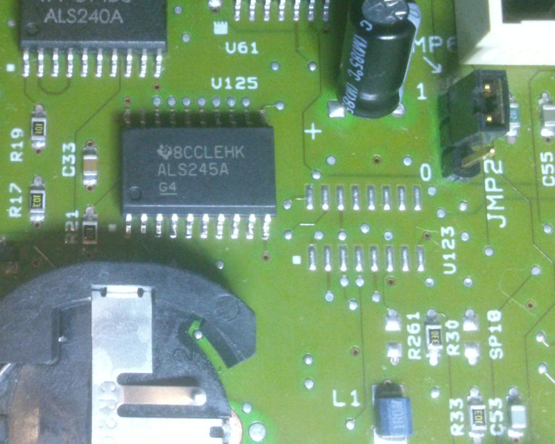
Picture 2: Top side of the board, U125 installed
That's done. Time to put everything back together and fire the beast up!
Aaaand... nothing. No checkpoints, just a blank display. Bummer. Hmm, so
something is quite obviously wrong or still missing.
I feel quite confident about the 74ALS245 choice, the soldering looks good
as well, and the chip is getting warm. Let's do some more "cold" probing before
we bring out the big guns (scope and logic analyzer). I was still a bit nervous
about the other unpopulated IC - U123. We know it's not wired directly to the
panel connector, but perhaps I've got too excited about the already populated
U124... Maybe U123 is part of the address logic as well? And sure enough, the
display write enable lines go through the U124 driver first, and then to the
missing U123 chip. Dangit, I should have measured this straight away. Oh well,
let's figure out what kind of glue is missing there.
Since it's the write enable lines that is being passed to U124 - signals
that can't be wired directly to the planar I/O address bus, it would make sense
to have some sort of demultiplexer IC at that place. There are many types of
demultiplexers in the 74xx family however. So let's check what info can we dig
about the missing part. Based on its footprint we can tell that the package we
are looking for is SOIC-16. We know how many devices are we driving - only 2,
but that piece of information doesn't help us one bit unfortunately, as all
demultiplexers will be capable of driving two lines. Now, the display unit
datasheet and the Op Panel pinout tell us that the write enable signals are
active low, and since there aren't any other gates in the path, we are looking
for "inverting" demultiplexer (inactive outputs are high, active input is low).
That narrows it down a bit, but not enough to give us a clear answer.
Let's check the other planars to see if we can find anything that would fit.
The 8595 planar has one 74F138 near the top edge, but it seems to be driving
something else... and that's it, nothing else suitable on either planar. They
probably realized the logic differently there. Well, 74F138 is a "3- to 8-Line Inverting
Decoder/Demultiplexer", so it still may be our part! If we compare the pinout
with wiring on the 9585 board, we will see, that location of outputs 0 and 1
matches location of the display write enable signals. The 74xx logic requires
that all inputs must be driven low or high for a reliable operation. Outputs
can be left floating. So we could check if this requirement is met for our
assumed "74F138". We are dealing with a multilayer PCB, but thankfully the IC
is a SMD part and IBM doesn't hide vias under pads, so we can clearly see what
is connected and what isn't. Good news, all inputs are wired to something, and
the only unconnected pins are outputs... great! I was also able to trace one of
the address inputs to planar address line A2 (by measuring on the nearby FDC
chip). So I think we have the right part here. There is also at least one other
demultiplexer that would meet our requirements - 74F137. It's actually fairly
similar, but it comes with address latching, which I don't think is needed
here. And it's not as common, so I would stick with 74F138. We know that the
pinout matches pretty much perfectly, therefore we can't really damage
anything, worst case scenario... the display won't work. Well, let's order a
few of them (never buy just one, you never know... and sometimes you have to
take at least 5 or 10 anyway) and solder one in.
Oy, keep that soldering iron hot, we are not done here yet. One of the pins
is going to position R261, where is supposed to be a SMD resistor. It's missing
but thankfully it's just a pull-up for one of the unused inputs. The value
isn't super critical in most scenarios, and as long as we are in the ballpark,
we will be fine. For the 74xx family a typical pull-up is 10 kohm and typical
pull-down 100 ohms. If we look around the planar we will see that IBM largely
sticked to this rule as well. So let's put one 10 k resistor to position R261.
It's just your every day 0805 thick film SMD chip. (No need to order this
puppy, I've plenty of them.)

Picture 3: Top side of the board, all 3 parts installed
(That resistor ain't crooked... It's the camera angle I swear!)
Ok, let's put this thing back together again, power it up, and... still nothing.
This time I've realized pretty quickly what was probably the issue here...
Yep, I've forgot to check the other side of the board for more passives. To get
a clear view of the other side of the board, and to make soldering actually
possible, it's necessary to remove the plastic support frame first. There are
quite a few unpopulated resistors and caps in that area actually. But only two
of them - R262 and R263 - seems to be directly related to the LED display
driver logic.
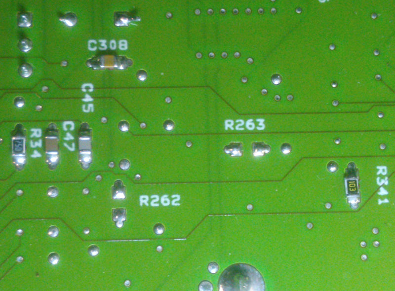
Picture 4: Bottom side of the board, unpopulated positions R262 and R263
R242 is a pull-down for another input of our friend U123 - so we should add
one 100 ohm resistor there. R263 sits between enable pins of U123 and U125, and
it's probably supposed to be somewhere in the 30 - 70 ohm range. I couldn't
find my 64 ohm reel, so I've used a 100 ohm one.
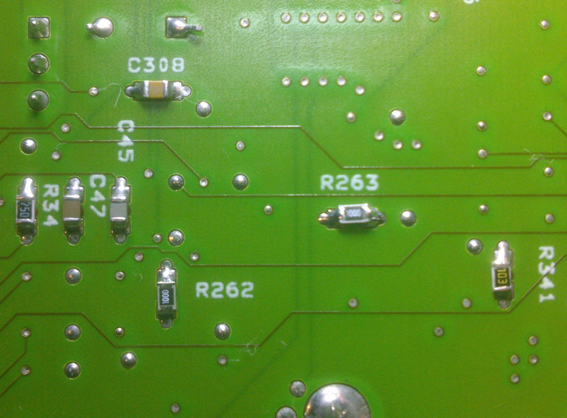
Picture 5: Bottom side of the board, both parts populated
That should be all here, so let's reinstall the support frame and put it all
back together again.
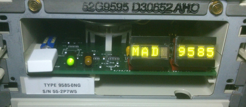
The third time is the charm. Power switch on, and... tadaa - "CP: 10"... and
then some error codes. Which is a good thing in this case, a bunch of stuff is
missing from the machine, but we can see that all digits are working
perfectly!

Picture 6: Operator Panel carefully balanced on top of the PSU. It works!
Time to clean up our work, and reassemble the machine properly.
Results
The Op Panel is fully operational when connected to the modified planar. The BIOS prints checkpoint and error codes to it during the POST process. It will also display the "96-8N1" serial terminal string when enabled. One thing that is missing when compared to the Model 95 BIOS is the CPU frequency string, that is normally displayed at the end of the POST process, before the machine starts loading your operating system. That's not a big deal however, since ports 108 - 10Fh can be used to display custom text.
Picture 7: All done, well almost...
Parts and equipment needed
List of parts required for the planar mod:
| Position |
Type/Value |
Description |
Package |
| U123 | 74F138 | 3-Line To 8-Line Decoders/Demultiplexers (inverting) | SOIC-16 |
| U125 | 74ALS245 | Octal Bus Transceivers With 3-State Outputs | SOIC-20 |
| R261 | 10 kohm | (thick) film SMD resistor | 0805 |
| R262 | 100 ohm | (thick) film SMD resistor | 0805 |
| R263 | 30 - 70 ohm | (thick) film SMD resistor | 0805 |
List of other equipment and tools needed or recommended for this job:
- PS/2 9585-K/N (obviously)
- PS/2 9595 Op Panel + bezel (unless you wanna modify the original one)
- Soldering iron with a small tip or hot air rework station
- 6 mm (1/4") hex socket or flat-head screwdriver
- Flux
- Q-tips & isopropyl alcohol
- Tweezers
- Magnifying glass and a good light recommended
- Digital multimeter recommended (to check your work)
How To
Note: This tutorial assumes that you have some
basic SMD soldering skills. If you don't feel confident, practice on some less
valuable board first, or ask some hobbyist to do this for you.
Disclaimer: I'm not responsible for any damage or
lose that could happened to your machine, equipment or other properties! You
are doing this on your own risk!
Note: If your planar still has the leaky nichicon
caps, I recommend replacing them and removing any potential corrosion asap. Now
you have a good opportunity to do it, since we will be removing the planar
anyway.
Steps:
- Discharge yourself by touching some grounded metal object
- Disconnect all external peripherals and open the system unit
- Remove all MCA adapters
- Unplug all Molex connectors from the PSU, remove the PSU grounding strap (one screw), swing the PSU out, and remove it from the system unit
- Unplug all cables from the planar
- Unscrew the planar (10 screws total), tilt it slightly from the DASD side so it clears the PSU mounting stand, and slide it out
- Remove the CR2032 battery if you want to be extra careful (this will of course clear your system configuration)
- Locate the U123/U125/R261 positions on the top side of the board, near the Indicator Panel connector (see Picture 1), and clean the area using q-tips and isopropyl alcohol
- Hose the U125 solder pads with flux, align the 74ALS245 chip with the pads using tweezers (pin 1 is marked with a little dot on the board, and there should be a matching dot or stripe on the IC), and solder it in.
Note: Be careful around the battery holder and the pin header connectors, they would melt fairly easily.
Note: No need to add more solder, the pads should already have enough solder on them (flux will help with any surface oxidation).
- Repeat the previous step with U123 - 74F138
- Repeat the previous step with R261 - 10 kohm resistor ("polarity" doesn't matter for resistors)
- Clean any flux residue using q-tips and isopropyl alcohol
- Inspect your work (either visually using a magnifying glass, and/or with your multimeter)
- Turn the board upside down and remove the plastic support frame (the one that supports the MCA slots), it's attached at 3 different points
- Locate positions R262 and R263 on the bottom side of the board, near the Indicator Panel and battery holder solder points (see Picture 4)
- Clean the area using isopropyl alcohol
- Apply some flux to the R262 solder pads, align the 100 ohm resistor with them, and solder it in
- Repeat the previous step with R263 - 30 - 70 ohm resistor
- Clean the area once again and inspect your work
- Reinstall the support frame
- Reinstall the CR2032 battery, if removed
- Put the planar back to the chassis and screw it in.
Note: Make sure that the support frame pins and all screw holes are properly aligned with the main chassis before screwing it in, otherwise you may damage the board or the support frame (or both)!
Note: You may want to use only 2-3 screws (always populate at least the two screws next to the PSU connector) and skip some of the following steps for the first test.
- Replace the original 9585 Indicator Panel with the 9595 Operator Panel
- Plug in all planar cables
- Reinstall the PSU, reattach the ground strap and Molex connectors
- Reinstall your MCA adapters
- Close the system unit and reattach your peripherals
- Turn the system unit on
- Enjoy your fancy Operator Panel :)
|